IMAGER DUO SYSTEM INSTALLATION
Imager Duo Operator’s Manual
2.3
CAUTION
Route all connectors
carefully to avoid
pinching the cables.
To avoid tripping
over or
disconnecting
cabling, do not
place cabling near
foot traffic.
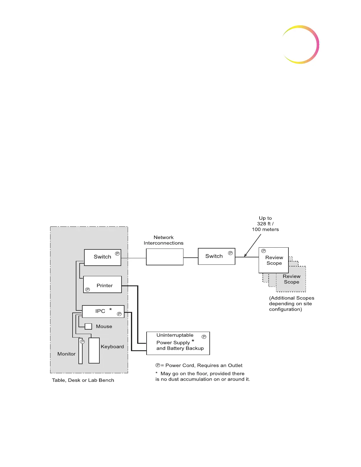
Extended Network Configuration
The Review Scopes may be located at a greater distance from the Image Proces-
sor by using an extended network interconnection between the Server hub and
the Review Scope hub.
Low-level, industry standard interconnection devices such as switches, bridges,
repeaters, media converters, copper and fiber wiring may be used. Refer to fig-
ure 2.2. The distance that Review Scopes may be located away from the Image
Processor is determined by the requirements of the specific apparatus used to
create the network. The throughput of the extended network must be capable of
10Mbps or greater.
Note:
High-level interconnecting devices (routers and gateways) and wireless
devices must not be used. The devices used for the extended network
must form an isolated network used exclusively for the Imaging System
network. No other company networks, sub-networks or devices may be
connected to the network.
Figure 2-2 Extended Network Interconnection Schematic (Example)
Component Configuration
The components may be arranged on the bench top as desired, providing the
connection cables can reach easily. The Image Processor Controller may be