Do you have a question about the Hologic QDR 4500 and is the answer not in the manual?
Contains confidential information and disclaimers regarding the use and servicing of the QDR 4500.
Lists revisions made to the document with dates and descriptions.
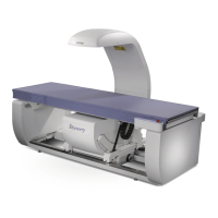
Describes the QDR 4500's function, dual-energy X-ray scanning principles, and results.
Explains the Q scan process, histogram analysis, and data discrimination.
Provides system block diagrams for Operator's Console, Scanner Unit, and C-Arm Subsystem.
Details system specifications including scanning method, X-ray system, detector, scanning sites, and weights.
Lists specifications for Half Value Layer, line voltage, current, maximum deviation, and measurement criteria.
Describes the QDR 4500 computer and the Communications Controller Board's function.
Explains the Distribution Board's interconnections and power supply details.
Details the function, power, and interconnections of Motor Controller and TZ Drive boards.
Describes the Control Panel Controller and C-Arm Interface boards' functions and interconnections.
Describes the X-Ray Controller Assembly, its boards, and interfaces with source units.
Details the Solid State Detector, Integrator/Multiplexor, and Analog To Digital Converter boards.
Describes FRUs within the Power Module and Operator's Console assemblies.
Lists necessary tools and documents for QDR 4500 installation.
Details minimum room dimensions and doorway widths for unit installation.
Procedures for uncrating the unit and moving it to its destination.
Critical safety warnings for high voltage, X-radiation, and ESD during installation.
Procedures for checking power line voltage and X-ray tube peak potential.
Steps for checking belt tension, C-arm Y belt adjustment, motor calibration, and X-ray beam alignment.
Procedures for measuring X-ray dose, leakage, scatter, and performing calibrations.
Steps for checking, aligning, and adjusting the table and its components.
Procedures for aligning the X-ray beam and performing beam flattening.
Guides for calibrating various motors (TZ, AY, TY, TX, AR) using SQDRIVER.
Procedures for adjusting A/D gain control and laser positioning offset.
Details the three stages for calibrating Area, BMD, and BMC measurements.
Procedure to verify lateral alignment of the system.
Lists the tools required for removing and replacing Field Replaceable Units (FRUs).
Procedures for FRUs in the Electronics Tray and C-Arm assemblies.
Procedures for FRUs related to Table X, Y, and Z motion.
Procedures for replacing Arm R components and the Gas Spring.
Procedures for FRUs located on the lower and upper C-arm assemblies.
Procedures for replacing FRUs within the Power Module and Operator's Console.
Procedures for FRUs in the Aperture and Drum Assemblies, including motors and belts.
Troubleshooting steps for power-related issues and locations of power components.
Troubleshooting steps for motion issues and locations of motion components.
Troubleshooting for control panel responsiveness and display issues (stripes, noise).
Troubleshooting for X-ray beam quality, laser, and targeting issues.
Procedure for addressing oil leaks and applying correct torque specifications.
Guide to understanding and troubleshooting various system error messages.
Required daily QC scans and database backups for customers.
Recommended annual/semi-annual maintenance procedures for trained service personnel.
Procedures for cleaning and greasing guide rails and bearings.
Summaries of LEDs, signals, sources, and jumpers for Power Distribution and ADC PCBs.
Summaries of Signal Distribution and Communications Controller PCBs.
Summaries for Detector Array, TZ Drive, Stepper Motor, and Control Panel Controller PCBs.
Summary of LEDs, signals, sources, and jumpers for the C-Arm Interface PCB.
Description of the SUSQ utility, how to start it, and its service screens.
Description of the SQKEYPAD utility for motor control and laser functions.
Step-by-step instructions for removing Hologic operating system software.
Step-by-step instructions for installing Hologic operating system software.
Procedure for cross-calibrating a new QDR system to an existing one.
Outline of the six essential steps for performing cross-calibration.
Checking original QDR calibration and archiving its patient database.
Verifying new QDR installation by performing scans and analyzing results.
Procedure to re-label the QDR phantom for daily QC on the new system.
| Type | Bone Densitometer |
|---|---|
| Category | Medical Equipment |
| Patient Weight Limit | 159 kg (350 lbs) |
| Detector | High-resolution digital detector array |
| Software | Hologic's proprietary software |
| Applications | Bone density measurement |
| Scan Regions | Lumbar spine, hip, forearm |
| Scan Modes | Single energy, Dual energy |
| Power Requirements | 100-240 VAC, 50/60 Hz |
