QDR
®
4500 Technical Manual
2-24
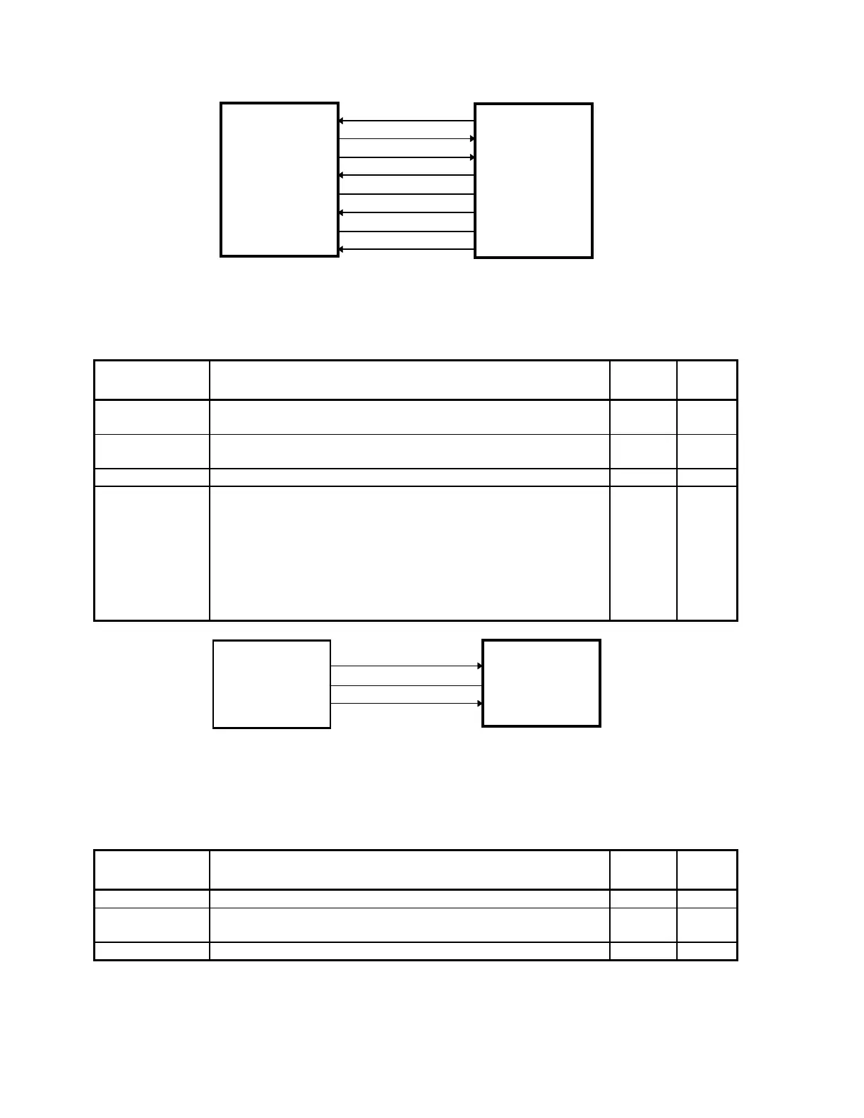
PFCREF+, PFCREF-
VES+, VES-
CURFAULT
+5V (P)
DGND (P)
+15V (P)
AGND (P)
-15V (P)
PFR
SUBSTITUTION
BOARD
I/O
and
LOGIC
Figure 2-11. PFR Substitution Board/I/O and Logic Board
Interconnection Diagram
Table 2-16. PFR Substitution Board/I/O and Logic Board
Interconnection Descriptions
Signal Description
PFR
Pins
IOL
Pins
PFRREF+
PFRREF-
Not used. JP5-2
JP5-3
JP3-2
JP3-3
VES+
VES-
Energy storage sense signal. JP5-5
JP5-6
JP3-5
JP3-6
CURFAULT Fault indicator (not used) JP5-8 JP3-8
+5V_(P)
DGRND_(P)
+15V_(P)
AGND_(P)
-15V_(P)
Provides power for the PFR Substitution board (not used). JP5-7
JP5-9
JP5-10,
JP5-11
JP5-12,
JP5-13
JP5-14,
JP5-15
JP3-7
JP3-9
JP3-10,
JP3-11
JP3-12,
JP3-13
JP3-14,
JP3-15
HDRIVEA
DGND (P)
HDRIVEB
I/O
and
LOGIC
H-BRIDGE
BOARD
Figure 2-12. I/O and Logic Board/H-Bridge Board Interconnection Diagram
Table 2-17. I/O and Logic Board/H-Bridge Board Interconnection
Descriptions
Signal Description
IOL
Pins
H-B
Pins
HDRIVEA Drive for H-Bridge transistors Q1 and Q2. JP5-1 JP2-1
DGND (P) Ground JP5-2
JP5-4
JP2-2
JP2-4
HDRIVEB Drive for H-Bridge transistors Q3 and Q4. JP5-5 JP2-5