Section 2 - Functional Description
2-9
ARD+, ARD-
ATD+, ATD-
SYSRESET+,
EMERGENCY+,
MAN_UP*, MAN_UP_RET
MAN_DOWN*, MAN_DOWN_RET
+24V
120V(A)_UP_LEFT
120V(A)_DWN_LEFT
120V(B)_LEFT
GND_PED
+3.0VREF
(Position Signal)
-3.0VREF
120V(A)_UP_RIGHT
120V(A)_DWN_RIGHT
120V(B)_RIGHT
GND_PED
+3.0VREF
(Position Signal)
-3.0VREF
TZ
DRIVE
BOARD
LEFT
PEDESTAL
MOTOR
To/From
Distribution Board
To/From
O
erator’s Console
Power Module
LEFT
PEDESTAL
POSITION
ENCODER
RIGHT
PEDESTAL
MOTOR
RIGHT
PEDESTAL
POSITION
ENCODER
120V(A)_RIGHT
120V(B)_RIGHT
GND_PED
120V(A)_LEFT
120V(B)_LEFT
GND_PED
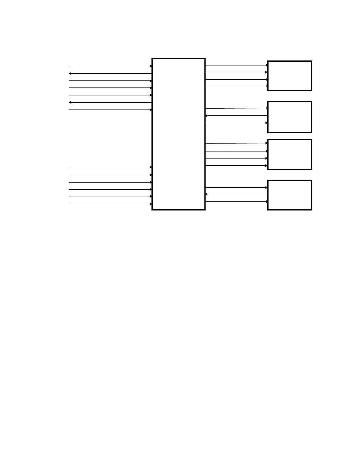
Figure 2-4. Distribution Board/TZ Drive Board Interconnection Diagram
Figure 2-4 shows the interconnections between the Distribution board, the TZ Drive Board, the
Pedestal Motors, and the Pedestal Position Encoders. Table 2-5 describes the interconnections
between the Distribution board and the TZ Drive Board. Table 2-6 describes the line voltage
(240VAC line to line) between the Operator's Console Power Module and the TZ Drive Board.
Table 2-7 describes the interconnections between the TZ Drive Board and the two pedestal
motors and their respective position encoders. The tables also identify the interconnection
connector and pin assignments.