QDR
®
4500 Technical Manual
2-16
Interface Connections
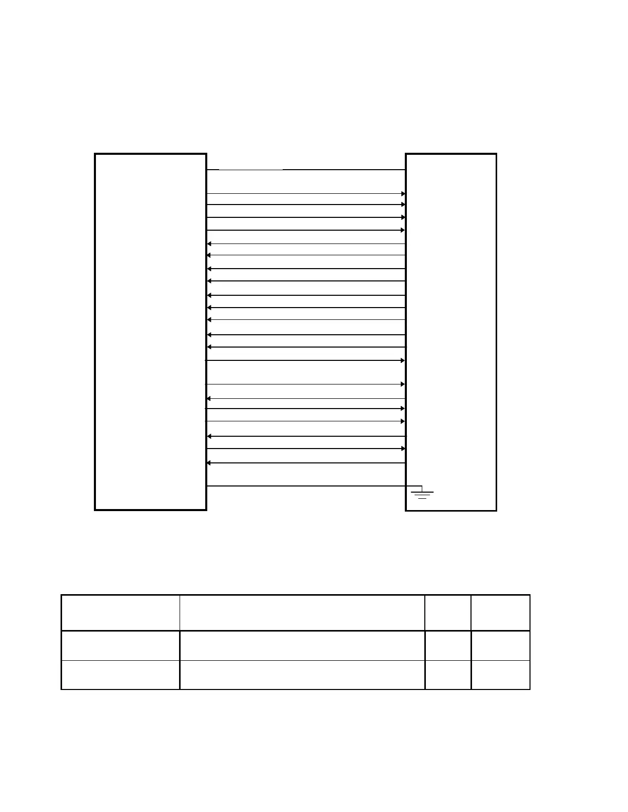
Figure 2-6 shows the interconnections between the Distribution board and the C-Arm Interface
board. Table 2-10 describes the interface signals and identifies the interconnection connector
and pin assignments.
ATD_CARM+, ATD_CARM-
STD+, STD-
STCLK+, STCLK-
STFRM+, STFRM-
ARD_CARM+, ARD_CARM-
SRD+, SRD-
SRCLK+, SRCLK-
SRFRM+, SRFRM-
EMERGENCY_CARM, EMERGENCY_CPANEL
LINESYNC+, LINESYNC-
INTEGRATE+, INTEGRATE-
SYSRST_CARM+, SYSRST_CARM-
EMERGENCY+, EMERGENCY-
XRAY_LIGHT+, XRAY_LIGHT-
+15V
15V_RET
-15V
24V
24V_RET
28V
28V_RET
C-ARM
INTERFACE
BOARD
DISTRIBUTION
BOARD
CONTINUITY 1
CONTINUITY 2
Figure 2-6. Distribution Board/C-Arm Interface Board
Interconnection Diagram
Table 2-10. Distribution Board/C-Arm Interface Board Interconnection
Descriptions
Signal Description
Dist
1
Pin
C-ARM
2
Pin
ARD_CARM+
ARD_CARM-
Asynchronous data to the C-Arm Interface board. JP1-3
JP1-4
JP1-3
JP1-4
STD+
STD-
Synchronous data through the C-Arm Interface board to
the DAS.
JP1-6
JP1-7
JP1-6
JP1-7