Section 4 - Alignment & Calibration
4-7
The next 5 steps adjust the beam side to side.
WARNING:
The X-rays are on. Keep body parts out of the beam.
1.
Move the
front
Filter Drum Allen alignment screw until the X-ray signal peaks.
Note:
The last direction turned should be clockwise to eliminate backlash when the jam nuts are
tightened. The plot should show peak amplitude.
2.
Move the
back
Filter Drum Allen alignment screw until the X-ray signal peaks.
Note:
The last direction turned should be clockwise to eliminate backlash when the jam nuts are
tightened. The plot should show peak amplitude.
3.
Tighten the jam nuts on both Filter Drum Allen alignment screws.
Note:
The X-rays should still show peak amplitude.
4.
Turn off the X-rays.
5.
Remove the alignment test fixture.
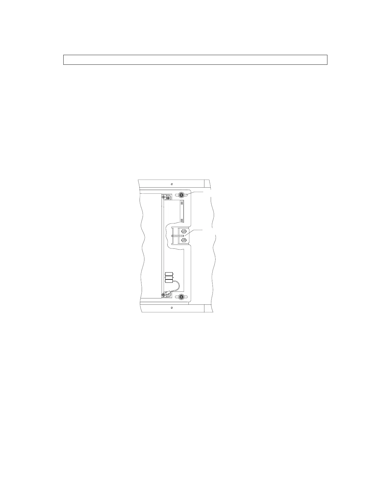
X-Ali
nm
n
N
4x
Figure 4-7. Array Assembly - Top View, Partial
The next 6 steps adjust the beam front to back.
1.
At the Array assembly, loosen the four X-alignment nuts (see Figure 4-7 above).
2.
Turn on the X-rays. Adjust the array X-alignment screw in one direction until the trace
drops off (the signal on the end detectors of the array will drop off). Then, count the
turns while moving it in the other direction until the trace falls off on the detector on the
other end of the array. Set the adjustment in the middle by turning the screw back half
the number of turns counted.
3.
Tighten the four array X-alignment nuts.