QDR
®
4500 Technical Manual
2-12
Interface Connections
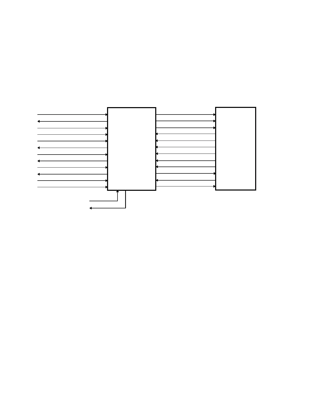
Figure 2-5 shows the interconnections between the Distribution board, Control Panel Controller
board and the Operator Control Panel. Table 2-8 describes the interconnections between the
Distribution board and the Control Panel Controller. Table 2-9 describes the interconnections
between the Control Panel Controller and the Operator Control Panel. The tables also identify
the interconnection connector and pin assignments.
ARD+, ARD-
ATD+, ATD-
SYSRESET+, SYSRESET-
EMERGENCY+, EMERGENCY-
XRAY_LIGHT+, XRAY_LIGHT-
MAN_TZ_UP
MAN_TZ_UP_RET
MAN_TZ_DOWN
MAN_TZ_DOWN_RET
EMERBENCY_PANEL
HW_EMERGENCY_RET
+7V
L0_PWR* - L7_PWR*
TZ_PWR*
XRAY_LIGHT_PWR*
SW0 - SW2
SR0 - SR2
MAN_TZ_UP
MAN_TZ_UP_RET
MAN_TZ_DOWN
MAN_TZ_DOWN_RET
EMERGENCY_PANEL
HW_EMERGENCY_RET
+5V
CONTROL
PANEL
CONTROLLER
OPERATOR
CONTROL
PANEL
To/From
Distribution Board
TILT_A
TILT_B
To/From
C-Arm
Tilt Switch
Figure 2-5. Control Panel Controller Interconnection Diagram