QDR
®
4500 Technical Manual
2-18
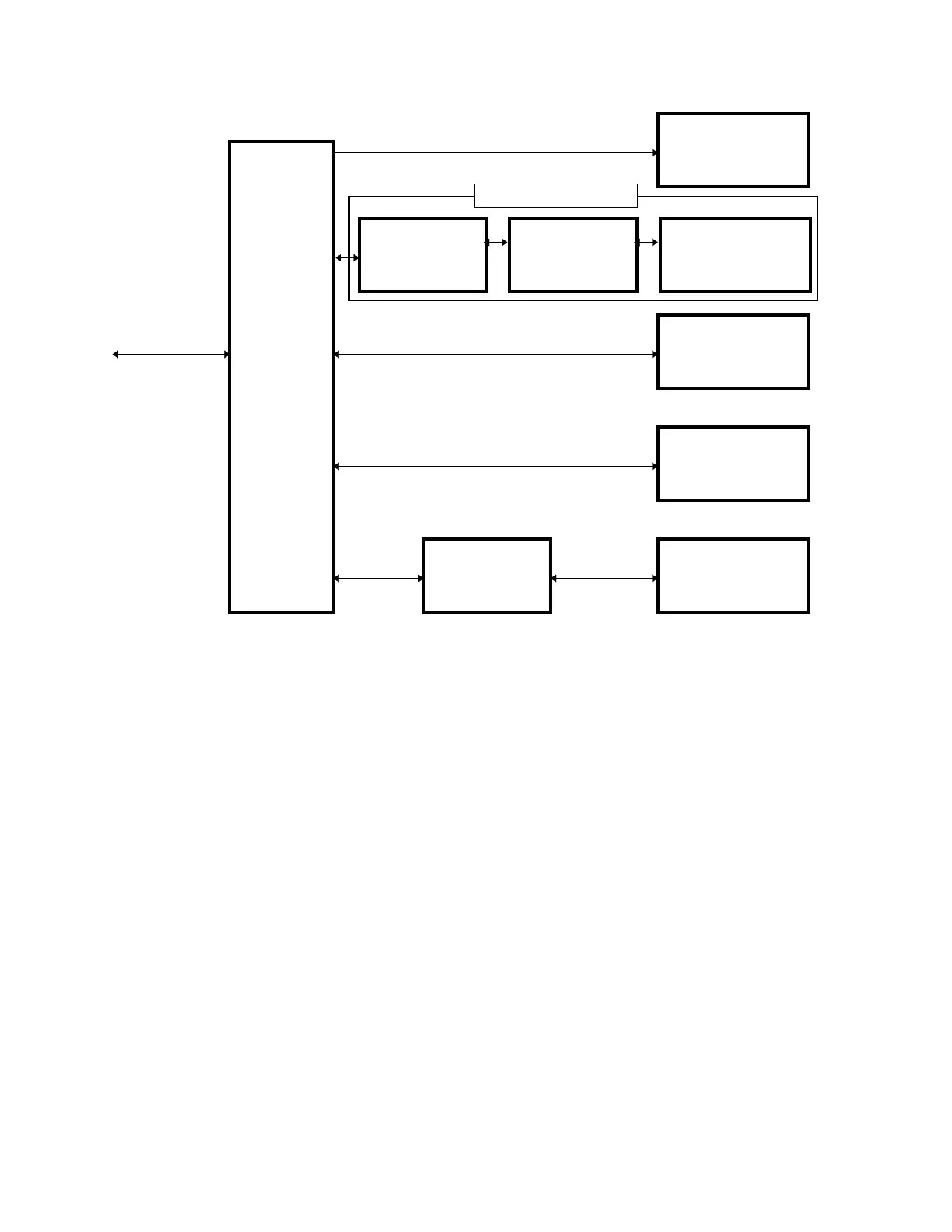
C-ARM
INTERFACE
X_RAY
SOURCE
UNIT
X-RAY
CONTROLLER
APERTURE
MOTOR AND
SENSOR
LASER
ASSEMBLY
DRUM
MOTOR AND
ENCODER PICKUP
TO/FROM
DISTRIBUTION
ANALOG TO
DIGITAL
CONVERTER
INTEGRATOR
MULTIPLEXOR
SILICON
DETECTORS
Data Ac
uisition S
stem
Figure 2-7. C-Arm Interface Board High Level Interconnection
Diagram
X-RAY CONTROLLER ASSEMBLY
The X-Ray Controller (XRC) assembly provides pulsed power to the primary winding of the high
voltage transformer in the X-Ray Source Unit and AC power to the primary winding of the
filament transformer. It consists of five printed circuit boards and several large components
contained in a chassis mounted at the front of the lower C-arm just in front of the Tank
Assembly. The five boards are the I/O and Logic, Low Voltage Power Supply, H-Bridge, Power
Factor Regulator (PFR) Substitution, and Duty Cycle Driver.
The XRC receives split 240VAC power from the Operator's Console Power Distribution Module.
It also receives command and timing data from the C-Arm Controller board and it provides a line
frequency timing signal and housekeeping and diagnostic data to the C-Arm Interface board.
Interface
Figure 2-8 shows the interface connections between the C-Arm Interface board and the X-Ray
Controller Assembly. Table 2-11 describes the interface signals and identifies the