Section 5 - Remove & Replace
5-5
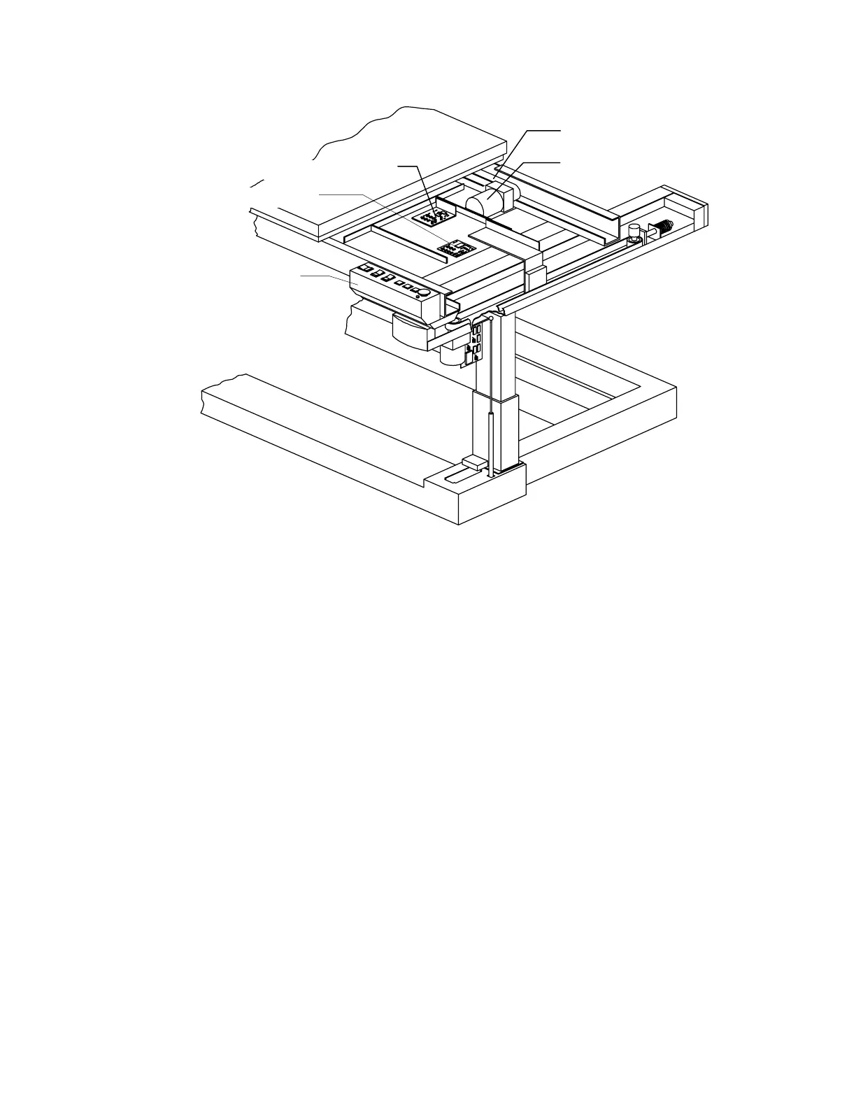
Motor Controller Bd
Table Y Belt
Table Y Motor
Control Panel PCB
Control Panel
Figure 5-2. Control Panel and Table Y FRUs
Control Panel
To remove and replace the Control Panel refer to Figure 5-2 and follow the procedure below:
1.
Turn off the QDR 4500 instrument power, computer power, and main circuit breaker.
2.
Remove 3 screws located under the Control Panel box.
3.
Unplug the cable (from the Control Panel to the Control Panel board) on the Control
Panel board and remove the panel.
4.
To replace the Control Panel reverse the steps.
PCBs Under Right-Side of the Table
To remove and replace the boards under the table (Motor Controller Board or Control Panel
Board) refer to Figure 5-2 and follow the procedure below:
1.
Unplug the cables on the board to be replaced.
2.
To remove the board, unscrew the Phillips screws holding the board
Note:
Some boards have standoffs and/or plastic hold-down snaps.
3.
To replace the board reverse the steps.