QDR
®
4500 Technical Manual
3-8
9.
Remove the table top by carefully sliding it off the front (requires two people).
Be
careful not to slide the bearing blocks off the rail.
10.
Refer to Figure 3-7. Install the right angle bracket (found in the miscellaneous hardware
kit) to hold the bearing blocks and X drive bracket, in place while the scanner is moved.
If this bracket is not available, tape the bearing blocks, and X drive bracket, in place.
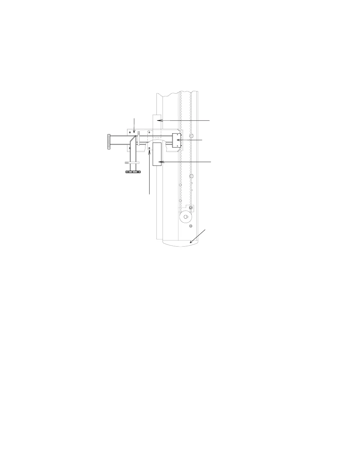
Stainless Ste
Cable Guard
X Drive Attachment Bracket
Front Endcap
Right Angle Bracket
Bearing Blo
Bearing Blo
Figure 3-7. Table X Drive
REMOVE QDR 4500A, OR SL, C-ARM (IF NECESSARY)
Note:
It is not necessary to remove the C-arm if the hallway(s) that the unit must go through is at
least 45" (114cm) wide (side to side inside dimension). Removing the C-arm allows the
unit to fit through a hallway 29" (74cm) wide.
The C-arm Carriage Assembly can be removed before taking the unit off the pallet. Follow the
procedure below to remove the C-arm:
1.
Remove the 2 carriage-to-base shipping brackets (see Figure 3-12).
2.
Remove the table locking "L" bracket located on the left side of the scanner (see Figure
3-12).
3.
Move the table forward, remove the C-Arm Interface board cover, and remove the tank
cover. Then move the table back.
4.
Remove the X-Ray Controller Assembly (4 Phillips screws). See the
Remove and
Replace Procedures
section, of this manual, for detailed removal information.