Section 2 - Functional Description
2-33
Operator's Console and consists of a Main Power circuit breaker, a Power On indicator, an AC
line input isolation transformer, a Power Control Panel, a Power board, a +/-15VDC power
supply board, a 24VDC power supply board, and a computer power outlet.
ISOLATION
TRANSFORMER
and
VOLTAGE
SELECTION
COMPUTER
SWITCH
INSTRUMEN
T
COMPUTER
CIRCUIT
BREAKER
COMPUTER
SW CB
SW
MAIN
CIRCUIT
BREAKER
CB
+/-15V
POWER
SUPPLY
24V
SUPPLY
CIRCUIT
CB
DC
POWER
SUPPLY
X-RAY
CONTROLLER
CIRCUIT
BREAKER
CB
LEFT
PEDESTAL
CIRCUIT
BREAKER
CB
RIGHT
PEDESTAL
CIRCUIT
BREAKER
CB
X_RAY
RELAY
X-RAY, MOTOR
ENABLE
KEY LOCK
SWITCH
SW
AUX X-RAY
OUTLET
CIRCUIT
BREAKER
CB
INDICATOR
+/-15V
SUPPLY
CIRCUIT
BREAKER
CB
120
+/-15 VDC
24 VDC
120 VAC
120 VAC
240 VAC
240 VAC
X_RAY_ON
EMG24IN
2 PHASE
120 VAC
100/120/220 VAC
50/60 Hz
28 VDC
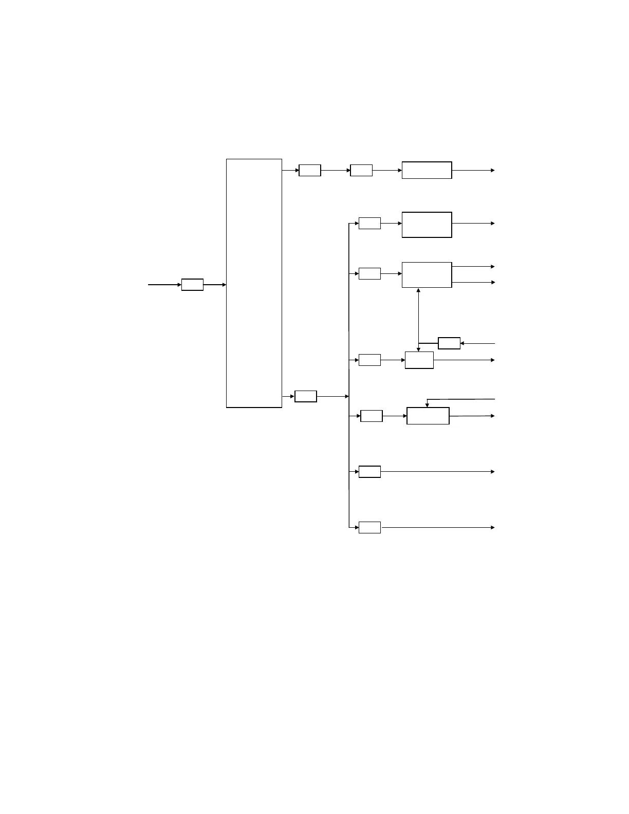
Figure 2-18. Power Module Block Diagram
The Main Power circuit breaker, Power On indicator, and computer power outlet are located on
the back of the Power Module near the bottom. The isolation transformer, Power Board, and +/-
15VDC and 24VDC power supply boards are located within the Power Module enclosure.
The Power Control Panel is the Power Module’s right side panel and it contains several circuit
breakers, switches, and indicators. It also contains a power outlet for connecting an external X-
Ray On light. Separate power switches are provided for the computer and the Scanner allowing
the computer to be operated separately. A key lock switch is used to switch power on/off to the
Scanner’s X-Ray unit, and to the stepper motors. The Power Module provides over current