Section 5 - Remove & Replace
5-25
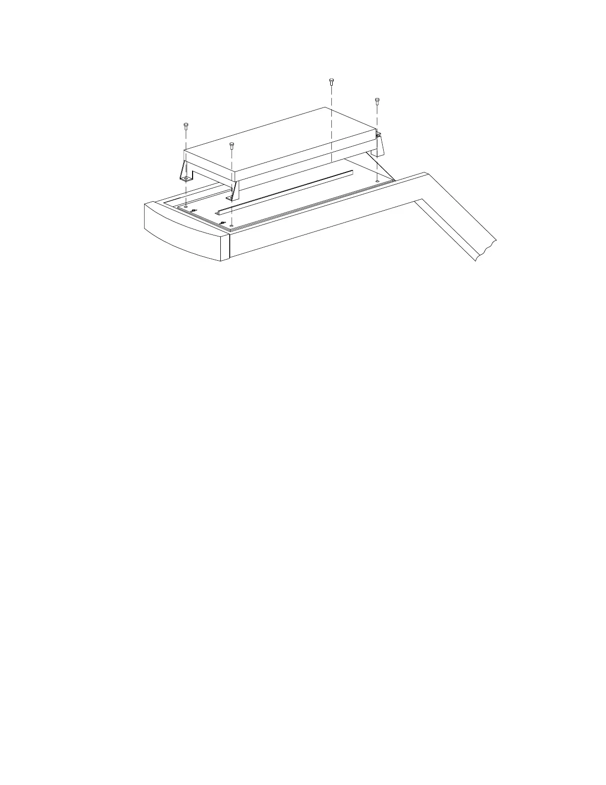
Figure 5-12. Detector Assembly Mounting
Laser Assembly
To remove and replace the Laser, or Laser Assembly, refer to Figure 5-12 and Figure 5-13 and
follow the procedure below:
1.
Turn off the QDR 4500 computer and instrument power switches, and main power
circuit breaker.
2.
Remove the top C-arm cover.
3.
Remove the three cables at the Mux board.
4.
Remove the 4 bolts holding the detector assembly (on rubber grommets) to the C-arm
(see Figure 5-12).
5.
Remove the detector assembly.