Section 5 - Remove & Replace
5-33
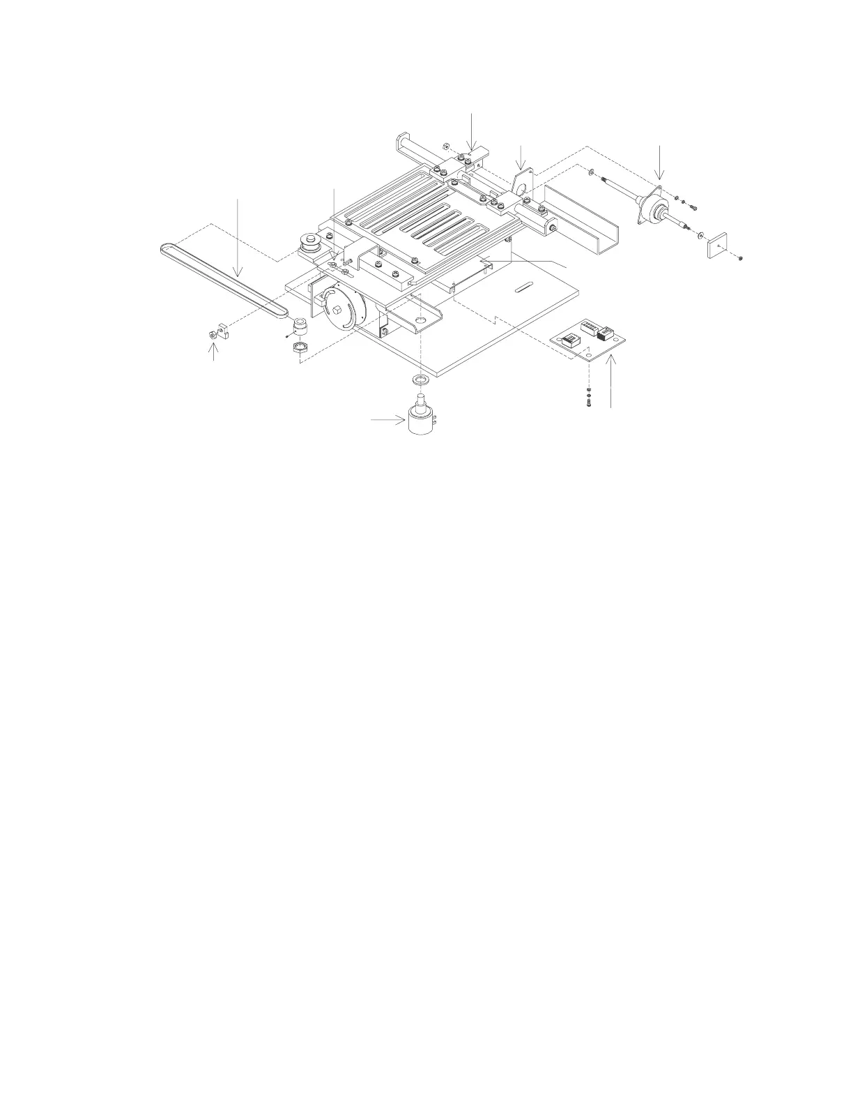
Rotary Potentiometer
Aperture Stepper Motor
Aperture Motor PCB
Position Belt
Motor Mount
Motor Shaft Bracket
Tension Nuts
PCB Bracket
Aperture
Clamping Nut
Figure 5-19. Aperture Assembly FRUs (QDR 4500A and SL)
Aperture Motor PCB
To remove and replace the Aperture Motor PCB (140-0068) refer to Figure 5-19
and follow the
procedure below:
1.
Remove the 2 Phillips screws from the motor shaft bracket.
2.
Move the aperture back far enough to expose the screws that hold the PCB bracket.
3.
Remove the 2 PCB bracket screws.
4.
Unplug the cables and install the new PCB on the bracket.
5.
Reverse the steps above to complete the installation of the new Aperture Motor PCB
assembly.
Aperture Position Belt
To remove and replace the Aperture Position Belt (255-0032) refer to Figure 5-19 below:
1.
Loosen the 2 belt tension nuts and the belt clamping nut.
2.
Remove and replace the belt (ensure the belt is under the pem stud).
3.
Tension the belt moderately tight (remove slack), and tighten the belt tension nuts.
4.
Remove the 2 Phillips screws from the motor shaft bracket.
5.
Rotate the belt pulley fully clockwise, then turn the pulley back 3/4 turn counter
clockwise (3/4 turn of the potentiometer pulley, not the idler pulley).

 Loading...


