QDR
®
4500 Technical Manual
2-32
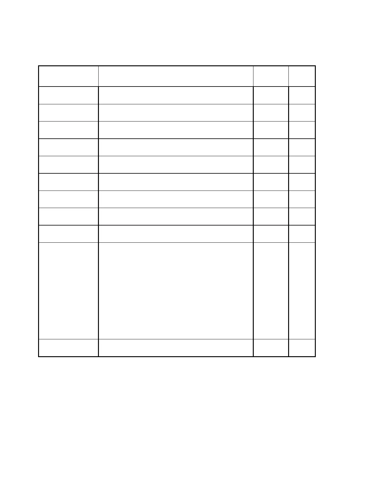
Table 2-23. C-Arm Interface Board/Analog/Digital Converter Board
Interconnection Descriptions
Signal Description C-Arm1
Pin
ADC2
Pin
STD+
STD-
Synchronous data to the Analog/Digital Converter board. JP10-3
JP10-4
P1-12
P1-13
STCLK+
STCLK-
Synchronizes data to the Analog/Digital Converter board. JP10-6
JP10-7
P1-15
P1-16
STFRM+
STFRM-
Synchronizes DSP Communications. JP10-9
JP10-10
P1-18
P1-19
SRD+
SRD-
Synchronous Data from the Analog/Digital board. JP10-12
JP10-13
P1-3
P1-4
SRCLK+
SRCLK-
Synchronizes data from the Analog/Digital Converter
board.
JP10-15
JP10-16
P1-6
P1-7
SRFRM+
SRFRM-
Synchronizes DSP Communications. JP10-18
JP10-19
P1-9
P1-10
SYSRST_DAS+
SYSRST_DAS-
Resets the Analog/Digital Converter board. JP10-21
JP10-22
P1-21
P1-22
INTEGRATE+
INTEGRATE-
Data integration signal. Generated by the C-Arm Interface
board.
JP10-24
JP10-25
P1-24
P1-25
XR_ZEROX_DAS+
XR_ZEROX_DAS-
AC line zero-crossing signal used for system wide
synchronization. Generated by the C-Arm Interface board.
JP10-27
JP10-28
P1-27
P1-28
+15V
-15V
15V_RET
+7V
Powers the Data Acquisition System.
JP10-32
JP10-33
JP10-36
JP10-37
JP10-30
JP10-31
JP10-34
JP10-35
JP10-38
JP10-39
P1-32
P1-33
P1-36
P1-37
P1-30
P1-31
P1-34
P1-35
P1-38
P1-39
CONTINUITY Emergency shutdown daisy chain (grounded on ADC
board)
JP10-1 P1-1
Notes: 1. C-Arm = C-Arm Interface board
2. ADC = Analog/Digital Converter board.
POWER MODULE
The Power Module provides the AC and DC voltages required by the QDR 4500 Operator's
Console computer system and Scanner. It is located in an enclosure in the bottom of the