5-1
SECTION 5
REMOVE AND REPLACE PROCEDURES
This section describes how to remove and replace the Field Replaceable Units (FRUs) in the
QDR 4500. To safely perform a FRU removal or replacement, take care to follow the procedure
precisely as written.
Note:
Whenever a component is replaced, you must rerun QC and recalibrate.
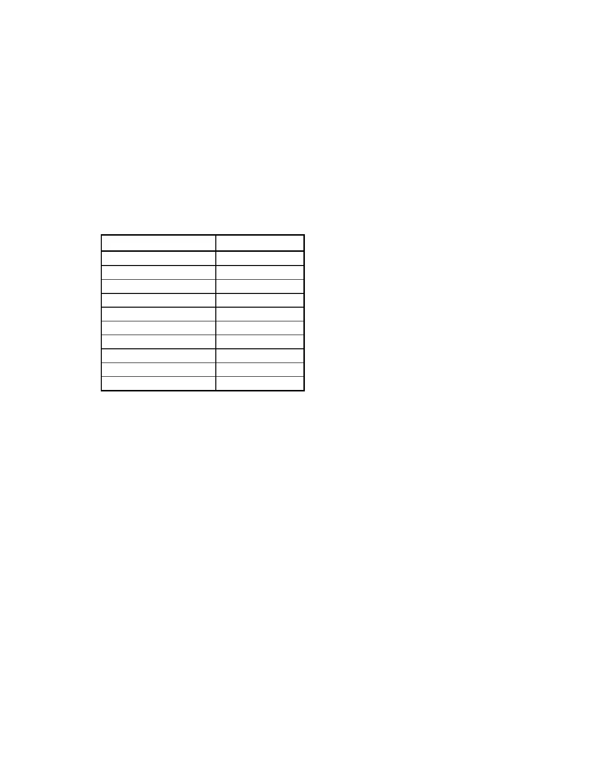
RECOMMENDED TOOLS
Tool Size/Type
Hex driver 3/32"
Hex driver or wrench 5/32"
Nut driver 1/4"
Nut driver 3/8"
Nut driver 5/16"
Nut driver 7/16"
Screwdriver Narrow slotted
Screwdriver Phillips head
Screwdriver Slotted
Wrench 3/8"
ELECTRONICS TRAY FRUS
This section describes how to remove and replace the FRUs in the Electronics Tray/Carriage
Drive area of the QDR 4500 (see Figure 5-1).
To remove any of the FRUs in the Electronics Tray assembly remove the 5 Phillips screws that
hold the tray cover and remove the cover.
Electronics Tray Printed Circuit Boards
To remove and replace the Distribution Board, Motor Controller Board, or TZ Drive Board refer
to Figure 5-1 and follow the procedure below:
1.
Move the C-arm all the way to the right.
2.
Turn off the QDR 4500 instrument power, computer power, and main circuit breaker.
3.
Remove the cable covers and unplug the cables on the board to be replaced.
4.
To remove the board, unscrew the Phillips screws holding the board
Note:
Some boards have standoffs and/or plastic hold-down snaps.
5.
To replace the board reverse the steps.