QDR
4500 Technical Manual
5-26
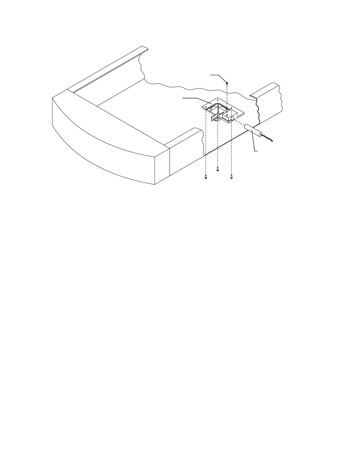
Laser Assembly
Laser
Laser Clamping
Screw
Figure 5-13. Laser Assembly
6.
To replace the laser only, loosen the laser clamping screw. To replace the laser
assembly remove the three mounting screws.
7.
To adjust the laser, loosen the laser clamping screw, turn the laser on and rotate it until
the correct alignment is seen.
REAR C-ARM FRUS
This section describes how to remove and replace the Analog to Digital Converter (ADC) Board
located on the rear C-arm (see Figure 5-14).
Analog to Digital Converter Board
To remove and replace the Analog to Digital Converter (ADC) Board refer to Figure 5-14 and
follow the procedure below:
1.
The C-arm should be in the AP position.
2.
Turn off the QDR 4500 computer and instrument power switches, and main power
circuit breaker.
3.
Remove the rear C-arm shoulder cover by removing 4 Phillips screws.
4.
Unplug the cables on the ADC board.
5.
Remove 4 Phillips screws, and remove the ADC board.