QDR
®
4500 Technical Manual
2-6
Interface Connections
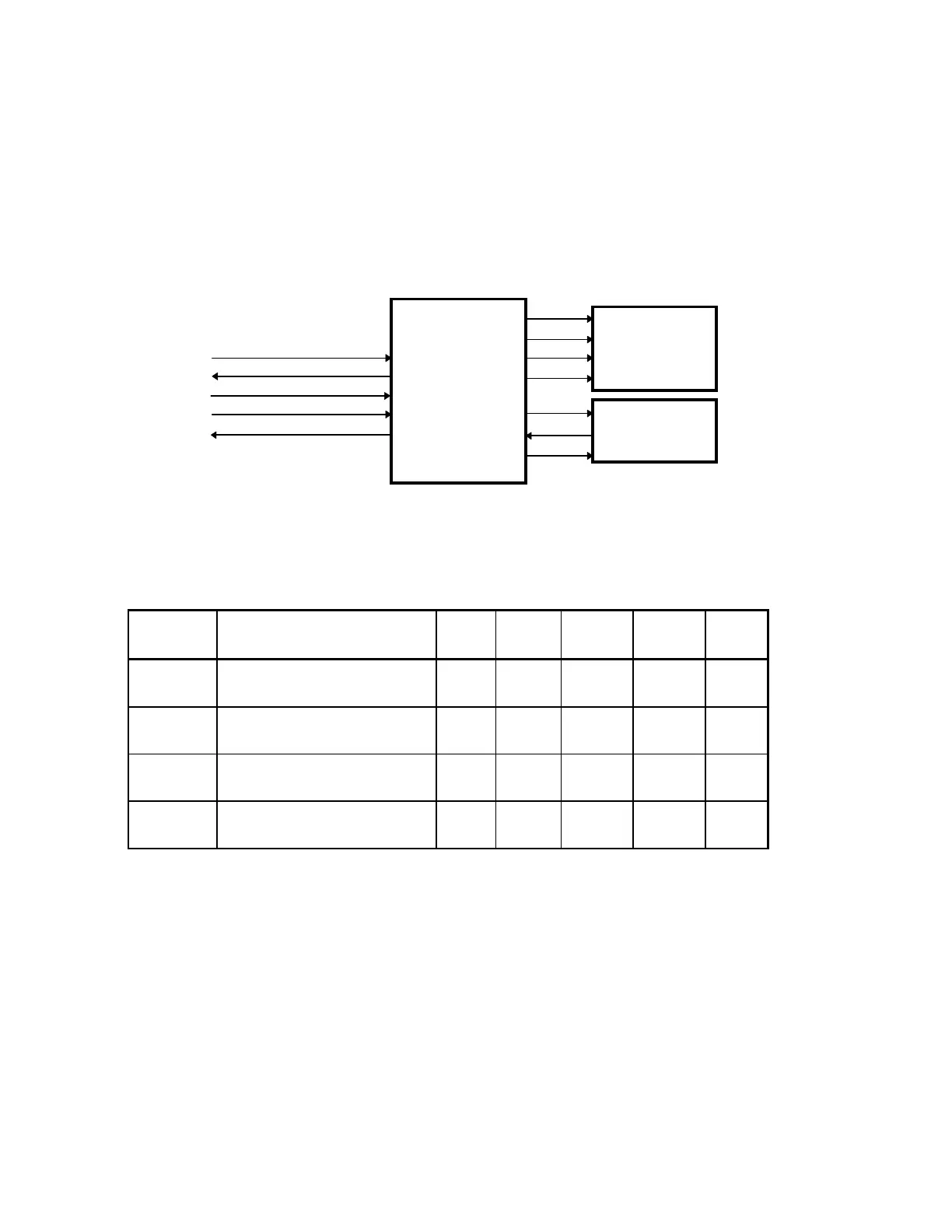
Figure 2-3 shows the interconnections between the Distribution board, the Motor Controller
boards, the Stepper Motors, and the Position Encoders. Table 2-1 describes the interconnections
between the Distribution board and the Motor Controller. Table 2-3 describes the
interconnections between each Motor Controller and its respective stepper motor and position
encoder. The tables also identify the interconnection connector and pin assignments.
ARD+, ARD-
ATD+, ATD-
SYSRESET+, SYSRESET-
+28V
28V_RET
(
)
(
)
(
)
(
)
+REF
(
)
-REF
MOTOR
CONTROLLER
STEPPER
MOTOR
To/From
Distribution Board
POSITION
ENCODER
Figure 2-3. Distribution Board/Motor Controller Board
Interconnection Diagram
Table 2-2. Distribution Board/Motor Controller Board
Interconnection Descriptions
Signal Description
Table
X
Table
Y
C-Arm
Rotate
C-Arm
Y
Pin(s)
ARD+
ARD-
Asynchronous Receive Data. JP7 JP5 JP8 JP11 11
12
ATD+
ATD-
Asynchronous Transmit Data. JP7 JP5 JP8 JP11 14
15
SYSRST+
SYSRST-
System Reset. Resets the Motor
Controller board.
JP7 JP5 JP8 JP11 17
18
28V
28V_RET
DC power for the Motor
Controller board.
JP7 JP5 JP8 JP11 2,3,4,5
1,6,7,8