QDR
®
4500 Technical Manual
2-2
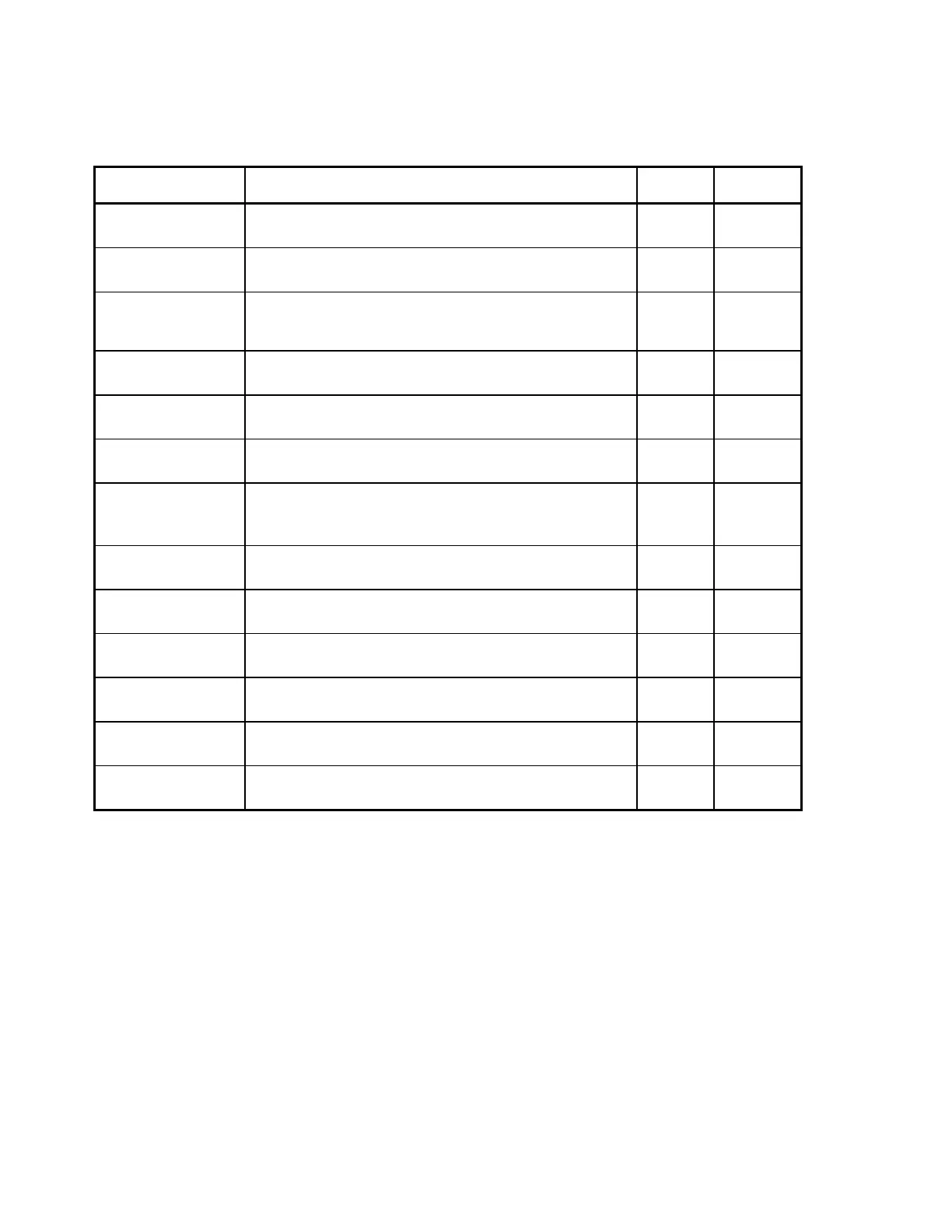
Table 2-1. Communications Controller Board/Distribution Board
Interconnection Descriptions
Signal Pair Description
CC
1
Pin
Dist
2
Pin
ATD+
ATD-
Asynchronous data to the Scanner.
JP1-2
JP1-27
JP10-3
JP10-4
STD+
STD-
Synchronous data to the Scanner. JP1-28
JP1-4
JP10-6
JP10-7
STCLK+
STCLK-
Synchronous data clock from Communications Controller
board to Distribution board. Synchronizes data to the
Scanner.
JP1-5
JP1-30
JP10-9
JP10-10
STFRM+
STFRM-
Synchronous data frame from Communications Controller
board to Distribution board.
JP1-31
JP1-7
JP10-12
JP10-13
ARD+
ARD-
Asynchronous Data from the Scanner. JP1-8
JJP1-33
JP10-15
JP10-16
SRD+
SRD-
Synchronous Data from the Scanner. JP1-34
JP1-10
JP10-18
JP10-19
SRCLK+
SRCLK-
Synchronous data clock from Communications Controller
board to Distribution board. Synchronizes data from the
Scanner.
JP1-11
JP1-36
JP10-21
JP10-22
SRFRM+
SRFRM-
Synchronous data frame from Distribution board to
Communications Controller board.
JP1-37
JP1-13
JP10-24
JP10-25
EMERGENCY_IN+
EMERGENCY_IN-
Signals an emergency condition. Generated by the C-Arm
Interface board.
JP1-14
JP1-39
JP10-27
JP10-28
ZEROX+
ZEROX-
AC line zero-crossing signal used for system wide
synchronization. Generated by the C-Arm Interface board.
JP1-40
JP1-16
JP10-30
JP10-31
INTEGRATE+
INTERGATE-
Synchronous signal for Detector Integrate period.
Generated by the C-Arm Interface board.
JP1-17
JP1-42
JP10-33
JP10-34
SYSRESET+
SYSRESET-
Resets the Scanner controllers. JP1-20
JP1-45
JP10-39
JP10-40
EMERGENCY+
EMERGENCY-
Removes power from the Scanner’s motor drivers and the
X-ray system
JP1-49
JP1-25
JP10-48
JP10-49
Note:
1. CC = Communications Controller board.
2. Dist = Distribution board.