Section 5 - Remove & Replace
5-39
15.
Install the spacers and pulleys at the front endplate (see Figure 5-21). Ensure that the
pulley set screws line up with the flat, and use Loctite 222 on set screws. Press the filter
drum against the fixture, and the pulley against the endplate, while tightening the set
screw.
Note:
Leave the outer pulley set screw loose until belts are installed.
16.
Remove the Drum Spacing Fixture.
17.
Replace the inner encoder wheel (see Figure 5-20). Press (squeeze together) the drum
and encoder wheel against the endplate and tighten the set screw (use Loctite 222).
18.
Replace the outer encoder wheel.
19.
Replace the drum encoder PCB. Ensure that the encoder wheels do not contact the
sensors.
20.
Replace the stepper motor assembly (2 screws on the motor mount, and 2 screws on the
base plate). Leave the motor mount screws loose for now.
21.
Replace the drum belts (see the Drum Belts procedure).
22.
Tighten outer pulley set screw after belts are installed.
23.
Refer to the Aperture Assembly procedure and install the aperture assembly.
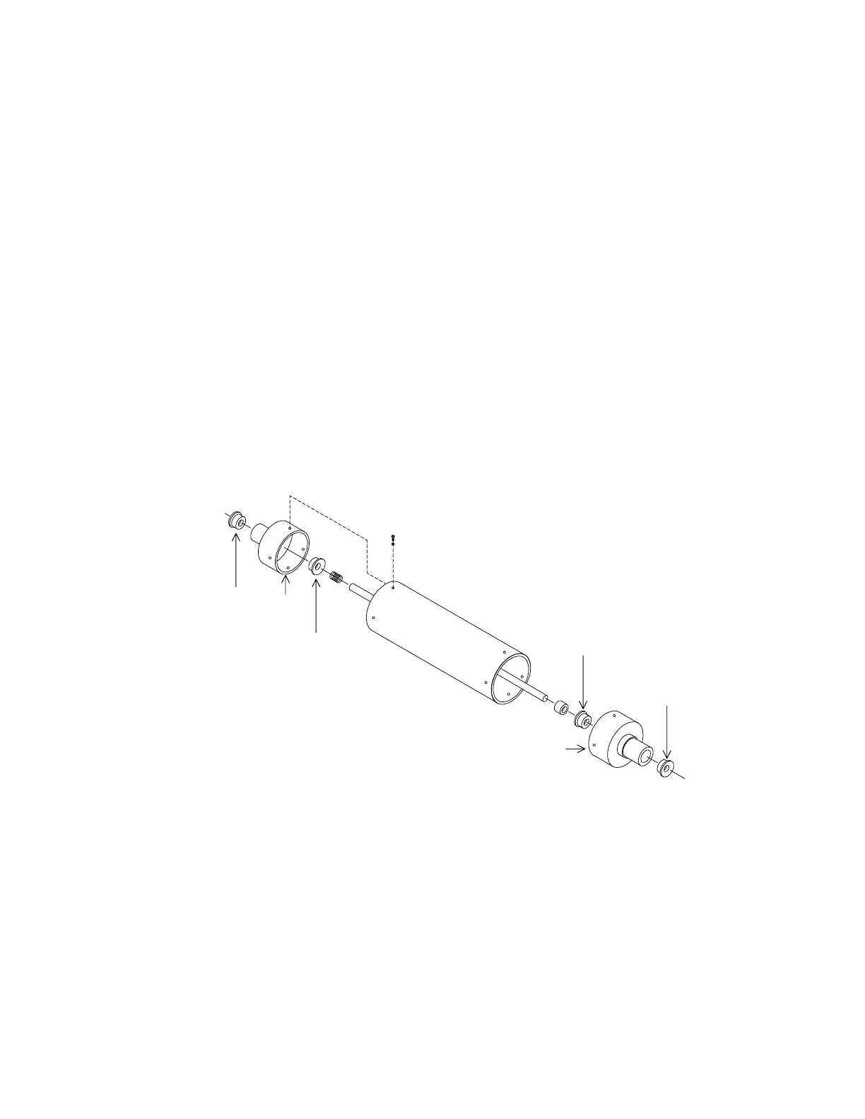
Bearing
250-0045
Bearing
250-0045
Bearing
250-0045
Bearing
250-0045
Endcap
Endcap
Figure 5-24. Drum Inner Bearings
REPLACING EMI CABLES
EMI cables are ribbon cables modified with braided shielding and ground lugs. When replacing,
be sure each ground lug is fastened to a ground connection, usually to the ground plane of the
PCB at that end. Use a star washer between the ground lug and the ground plane. Be sure the
ground lug does not short out any component on the PCB.