Section 2 - Functional Description
2-19
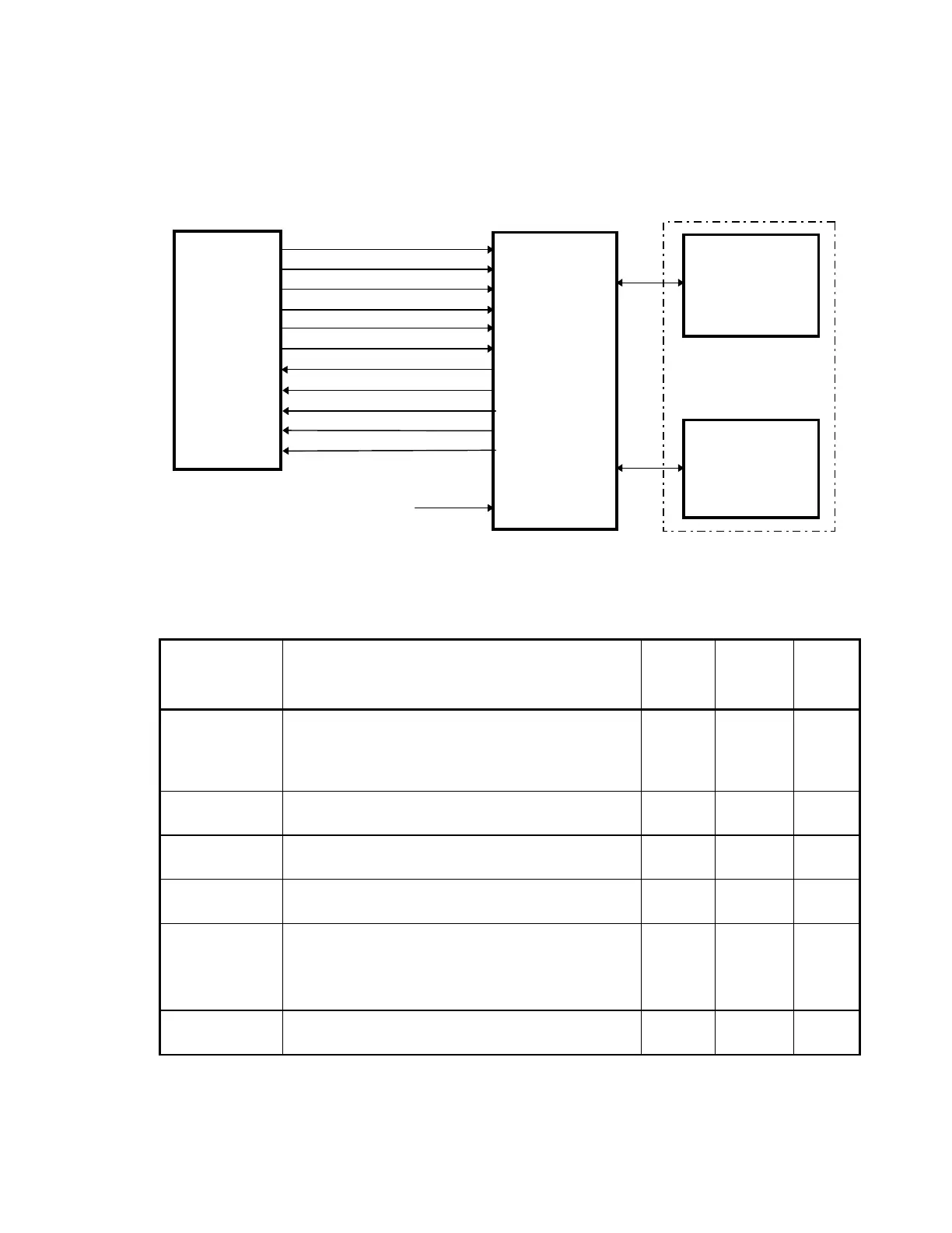
interconnection connector and pin assignments. Note that the AC input power comes directly
from the Operator's Console Power module and connects to the Low Voltage Power Supply
board of the X-Ray Controller Assembly. All others connect to the I/O and Logic board of the
assembly.
XR_RLY_ON+, XR_RLY_ON-
XR_FREQ+, XR_FREQ-
XR_BEAMON+, XR_BEAMON-
XR_ISET+, XR_ISET-
XR_KV1+, XR_KV1-
XR_KV0+, XR_KV0-
ACLINE+, ACLINE-
LIGHTON+, LIGHTON-
IBEAM+, IBEAM-
KVP+, KVP-
XRFAULT+, XRFAULT-
X-RAY
CONTROLLER
ASSEMBLY
C-ARM
INTERFACE
BOARD
HIGH VOLTAGE
TRANSFORMER
PRIMARY
X_RAY TUBE
FILAMENT
TRANSFORMER
PRIMARY
240 VAC
From Operator’s
Console Power Module
X-RAY
SOURCE
UNIT
Figure 2-8.
C-Arm Interface Board/X-Ray Controller Assembly Interconnection Diagram
Table 2-11. C-Arm Interface Board/X-Ray Controller Assembly
Interconnection Description
Signal Description C-Arm
Pins
I/O
Logic
Pins
XRC
Pins
XR_RLY_ON+
XR_RLY_ON-
Allows the energy storage capacitor to be “trickle
charged” before applying full power to avoid large
turn-on current surges that could cause the circuit
breaker to trip.
JP12-1
JP12-2
JP7-1
JP7-2
JP3-1
JP3-20
XR_FREQ+
XR_FREQ-
States whether the line frequency is 50 or 60Hz. JP12-3
JP12-4
JP7-3
JP7-4
JP3-2
JP3-21
XR_BEAMON+
XR_BEAMON-
Controls the ON/OFF status of the X-Ray beam. JP12-5
JP12-6
JP7-5
JP7-6
JP3-3
JP3-22
XR_ISET+
XR_ISET-
Selects the X-Ray beam current (3 or 10mA). JP12-7
JP12-8
JP7-7
JP7-8
JP3-4
JP3-23
XR_kV1+
XR_kV1-
XR_kV0+
XR_kV0-
Selects the X-Ray beam energy (80, 100, 120 or
140kVp).
JP12-9
JP12-10
JP12-11
JP12-12
JP7-9
JP7-10
JP7-11
JP7-12
JP3-5
JP3-24
JP3-6
JP3-25
ACLINE+
ACLINE-
States the phase of the power frequency. JP12-19
JP12-20
JP7-19
JP7-20
JP3-10
JP3-29