QDR
®
4500 Technical Manual
2-22
UNREG20V+
UNREG20COM
UNREG20-
UNREG20V+
UNREG20COM
UNREG20-
SW_120V_(A)
XR_120V_(N)
SW_120V_(B)
SW_ON*
AGND_(P)
AC_TICK
+5V_(P)
DGND_(P)
+15V_(P)
AGND_(P)
-15V_(P)
FIL120VAC_(N)
FIL120VAC_(A)
RELAY_PWR
RELAY+
I/O
and
LOGIC
BOARD
PFR
SUBSTITUTION
BOARD
DUTY CYCLE
DRIVER
BOARD
INTERLOCK
WIT
H
LOW
VOLTAGE
POWER
SUPPLY
BOARD
120VAC_(A)
120VAC_(N)
120VAC_(B)
From
Operator’s
Console
Power Module
ENERGY
STORAGE
CAP
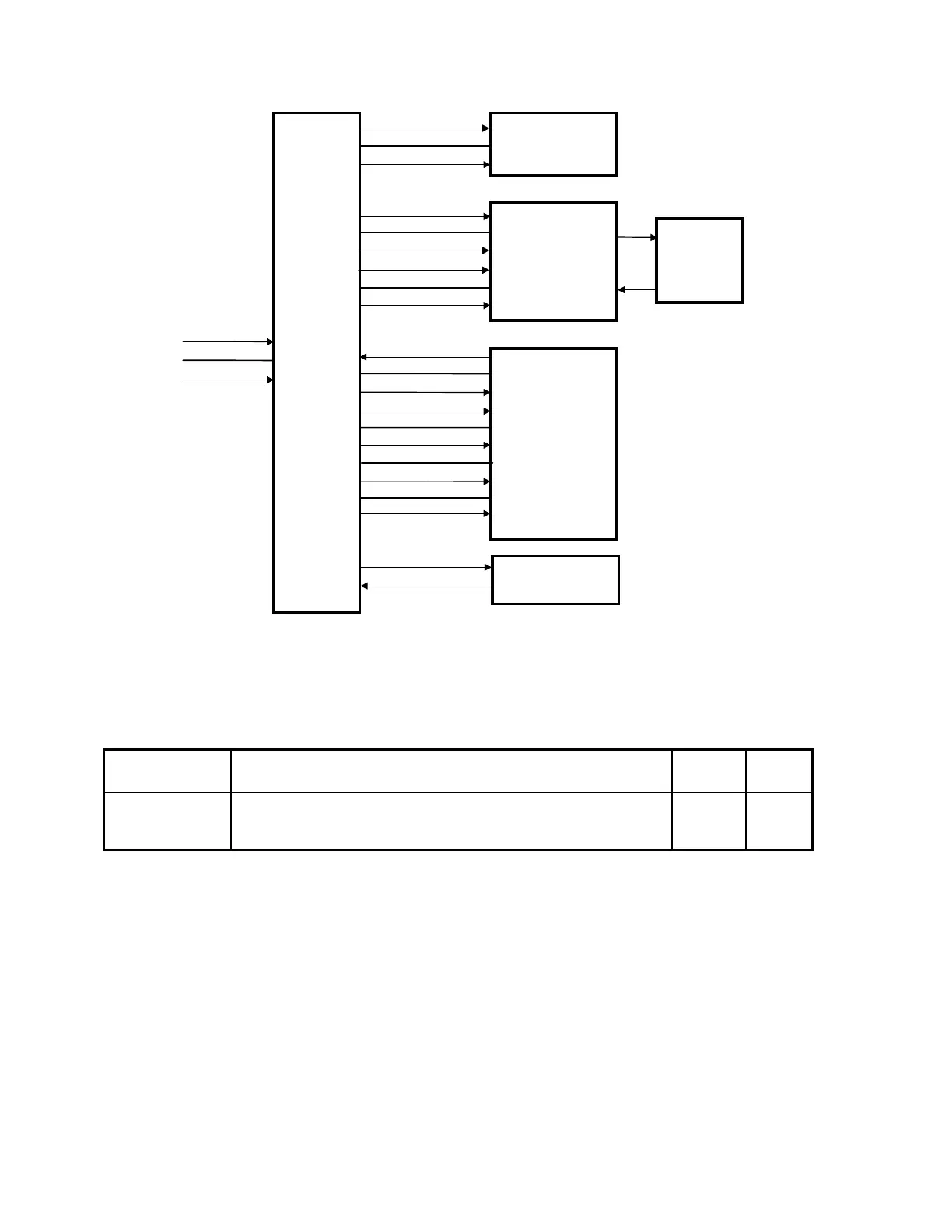
Figure 2-10. Low Voltage Power Supply Board Interconnections
The interlock switch, shown in the above figure, has two sets of contacts, one for relay power
(shown), and one for discharging the Energy Storage Capacitor (not shown).
Table 2-12. Low Voltage Power Supply Board/Duty Cycle Driver Board
Interconnection Description
Signal Description
LVPS
Pins
DCD
Pins
UNREG20V+
UNREG20COM
UNREG20-
Generates the regulated voltages used on the Duty Cycle Driver
board.
JP2-1
JP2-2
JP2-3
JP3-1
JP3-2
JP3-3