Section 6 - Fault Isolation
6-3
motion related problems. The following suggestions apply to a QDR 4500 system that exhibits a
motion problem.
Start by identifying the bad axis (if it is not obvious). Ask the operator for symptoms and check
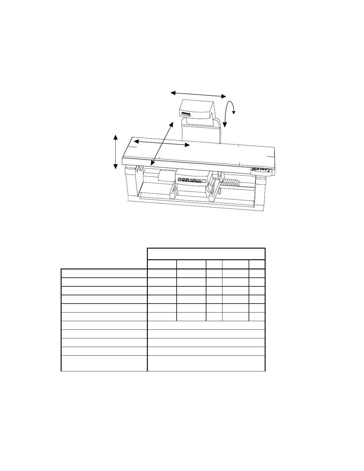
the error log. See Figure 6-1 for possible motion directions.
Scanner Unit
TX
TY
AY
AR
TZ
Figure 6-1. Scanner Motion Directions
Refer to the Figure Below
ARM-Y ARM-R TX TY TZ
Drive Belt
5-1 5-7 5-4 5-2,5-3
Drive Motor
5-1 5-6 5-4 5-2 5-5
Driver Board
5-1
Encoder
5-1 5-6 5-4 5-3 5-5
Encoder Belt
5-7
Motor Controller Board
5-1 5-6 5-4 5-2
Distribution Board
5-1
Oper Cntrl Panel
5-2
Control Panel PCB
5-2
Computer
5-16
Communications
Controller
5-17
Table 6-2. Motion Component Locations