Section 4 - Alignment & Calibration
4-5
(Place the block on the base plate next to the pin, and compare the pin to the vertical
surface of the block to better visualize whether the pin is perpendicular).
6.
Raise the pin from the base plate, but not out of the aperture plate. Insert the alignment
block and insert the pin through the block and back into the base plate alignment hole.
Move the aperture until the base of the block sits flat on the base plate.
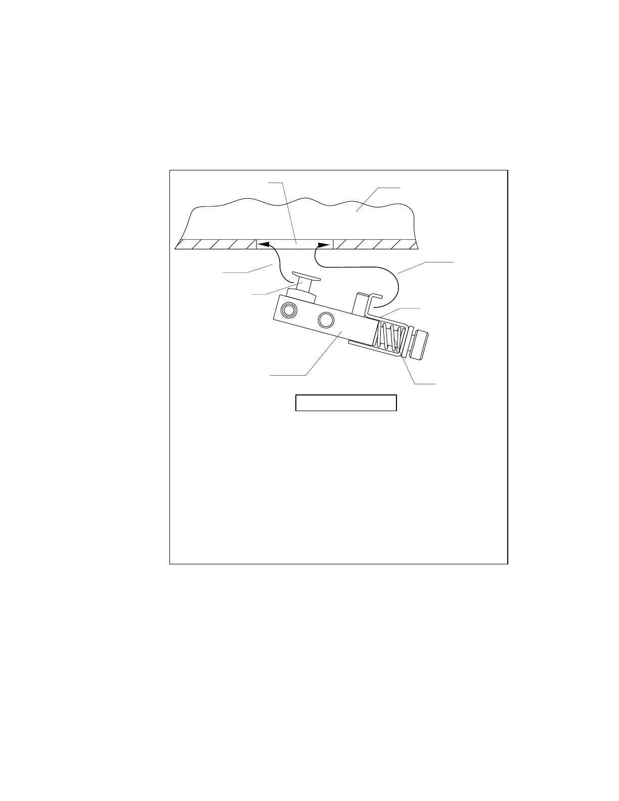
A
B, D
C
Fixture
C-Arm
Detector Opening
View from Front
Step A.
Insert the left side of the Alignment Fixture into the left side of the
Detector Opening so that the vertical edges of the four Alignment
Pins are secure.
Step B.
Compress the Holding Clamps.
Step C.
Raise the right side of the Alignment Fixture into the Detector
Opening.
Step D.
Release the Holding Clamps.
Note:
If the Alignment Fixture is inserted with the Alignment Pins on the
right, the procedure works equally well.
Holding Clamp
Alignment Pin
Figure 4-4. Inserting The X-Ray Alignment Fixture