QDR
®
4500 Technical Manual
2-4
Note:
+7VDC may measure anywhere from +6.25VDC to +7.25VDC. This is true everywhere
+7VDC is shown in this manual.
Six green LEDs indicate the status of the +28, +24, +15, -15, +7 and +5VDC (ON indicates the
respective voltage is present). Five red LEDs indicate the status of the five circuit breakers
applying voltage to the motor drivers/controller. ON indicates the circuit breaker has detected an
over-current condition.
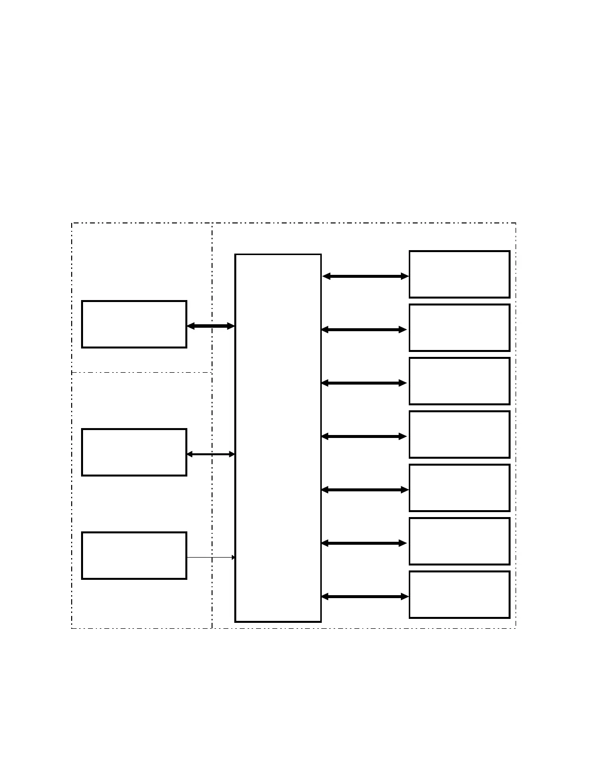
Interface Connections
Figure 2-2 shows boards that connect to the Distribution board.
DISTRIBUTION
BOARD
C-ARM
INTERFACE
BOARD
CONTROL PANEL
CONTROLLER
BOARD
TZ
DRIVE
BOARD
TX MOTOR
CONTROLLER
BOARD
TY MOTOR
CONTROLLER
BOARD
AR MOTOR
CONTROLLER
BOARD
AY MOTOR
CONTROLLER
BOARD
COMMUNICATIONS
CONTROLLER
BOARD
+24 VDC, +/-15VDC,
EMERGENCY
SIGNAL LINES
+28 VDC
OPERATOR’S
CONSOLE
COMPUTER
OPERATOR’S
CONSOLE
POWER MODULE
INSTRUMENT
Figure 2-2. Distribution Board High Level Interconnection Diagram