Section 5 - Remove & Replace
5-27
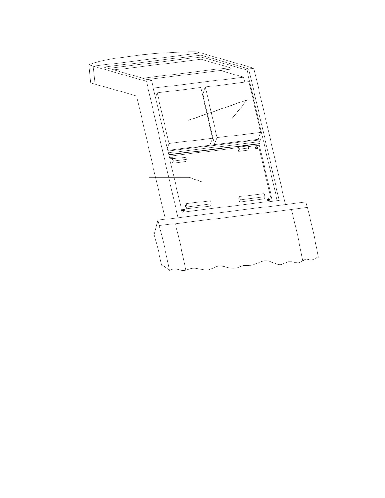
Counterweights
Analog to Digital
Convertor Bd
Figure 5-14. Rear C-Arm FRUs
6.
To replace the ADC board reverse the steps.
7.
Perform the A/D Gain Control Adjustment in the
Alignment and Calibration
section of
this manual.
8.
Perform Beam Flattening in the
Alignment and Calibration
section of this manual.
POWER MODULE FRUS
This section describes how to remove and replace the FRUs in the power module. The power
module is located at the bottom of the computer stand. Figure 5-15 shows a rear view of the
power module with the side panel removed.
28 Volt Power Supply
To remove and replace the 28V Power Supply refer to Figure 5-15 and follow the procedure
below: