QDR
4500 Technical Manual
8-4
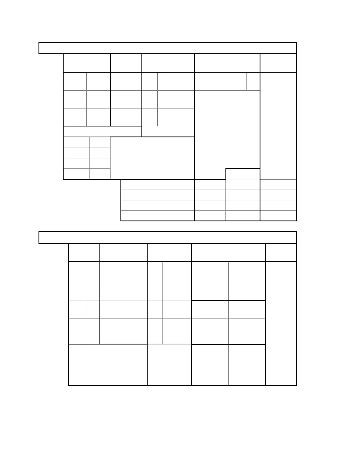
Stepper Motor Controller
LEDs Signal Source Jumpers and
Switches
Refer to...
D3 On +28VDC Ext Signal Dist. W1
(SYSRESET)
In
D6 On +5VDC Int. Voltage
Reg.
- - -5VDC Int. Voltage
Reg.
D7 (4 LED pack)
MEN On
Note:
All 4 LEDs are On
CPU Flash solid when the selected
DIR Off motor drive is engaged.
STEP Off
Set to...
Stepper motor (AR) SW1 6 Figure 5-6
Stepper motor (AY) SW1 7 Figure 5-1
Stepper motor (TX) SW1 4 Figure 5-4
Stepper motor (TY) SW1 5 Figure 5-2
Control Panel Controller
LEDs Signal/Voltage Voltage
Source
Jumpers Refer
to...
D1 On NLEVEL - - JP3
(OPER)
In
D2 On TAPE
SWITCH
-- JP4
(TEST)
Out Figure
5-2
D3 On +5VDC Int. Voltage
Reg.
JP1- JP5
(A/SL)
JP1- JP5
(W/C)
-- +7VDC Ext
.
Signal
Dist.
Connected
to tape
switches.
Tape
switch
eliminator.
Note:
D2 goes off when
tape switch is depressed.
Control
Panel
Emergency
SW.
Located on
Operator’s
Console.
Must be
UP.