QDR
4500 Technical Manual
4-4
5.
Tighten the bolts and repeat step 1.
6.
Replace the cover.
X-RAY BEAM ALIGNMENT (A and SL only)
It is crucial that the X-ray beam be precisely aligned with the detector, because improper
alignment will directly affect the repeatability (coefficient of variability, or CV) of the QDR
4500. Therefore this alignment must be verified at the time of installation or whenever any work
is performed that may affect it.
To check beam alignment:
WARNING:
X-rays are being generated during this procedure. Keep hands, head and other
body parts out of beam.
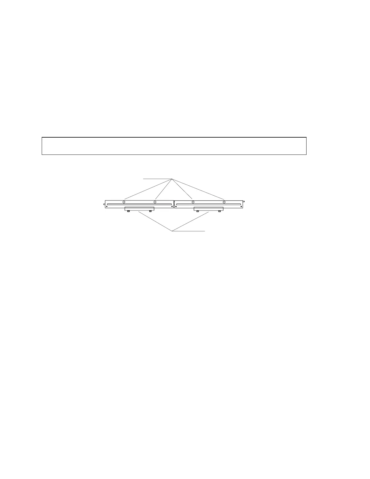
Insert the alignment fixture (see the following three figures) into the detector opening.
Alignment Pins
Holding Clamps
Figure 4-3. X-Ray Alignment Fixture (010-0923)
1.
Go to aperture #10 (use gain of “2” for high and “1” for low; use X-ray mode “3”).
2.
Turn the X-rays on (using SUSQ).
3.
Look at the monitor screen.
The correct display should be flat and have an amplitude of about six (6) volts. If the X-Ray
beam alignment is not correct, perform the following procedure.
1.
Remove the C-arm cover.
2.
Ensure that the upper C-Arm is parallel to the table (see
C-Arm Parallelism Adjustment
in this section).
3.
At the DOS prompt, type SQDRIVER. The SQDRIVER prompt is CARM$$$$>.
4.
At the SQDRIVER prompt, CARM$$$$>, type MOVE_APER_REL. Place the pin
through the alignment hole in the aperture. Move the aperture approximately 100 steps
at a time (If the tank cover is on, remove it.
5.
Move the aperture approximately 100 steps at a time (+100 moves right, -100 moves
left) until the pin drops easily into place through the alignment hole in the base plate.
Move the aperture until the pin is visually perpendicular to the base plate