6-1
SECTION 6
FAULT ISOLATION
This section provides information to help identify the source of a problem in the QDR 4500
system. The four general categories are:
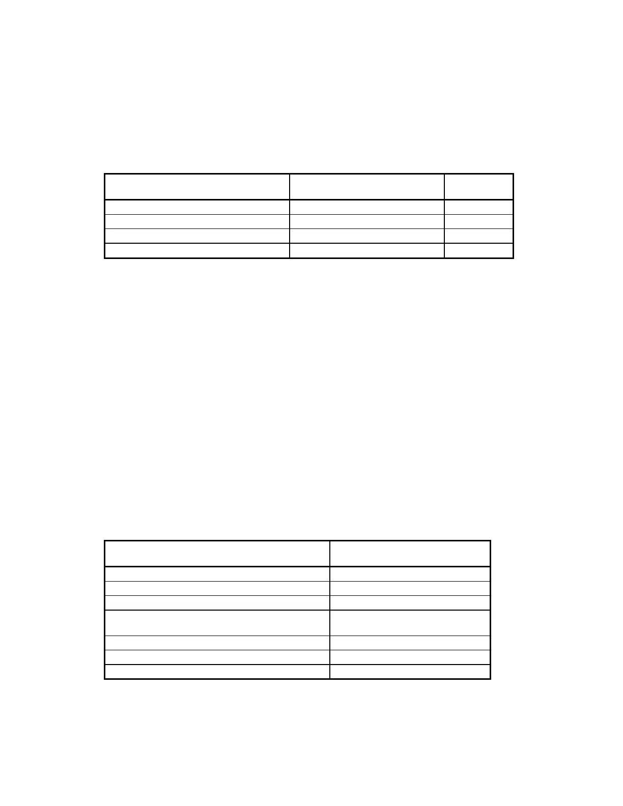
Problem... Refer to the section titled... On page...
Dead system, or power problem
Power Problems
6-1
Scanner motion problem
Motion Problems
6-2
Computer display problem
Display Problems
6-5
Error message displayed or logged
Messages
6-16
BEFORE STARTING
Before starting, make sure the software configuration is compatible with the scanner.
SOFTWARE CONFIGURATION
Check the release number at the top of the Hologic main menu to be sure that it is valid for the
scanner model.
HARDWARE CONFIGURATION
When troubleshooting, it is sometimes helpful to observe all the indicators available on the PCBs
and other FRUs. Many components of the system have LEDs indicating the presence of
necessary voltages and the state of some signals. Section 8 is helpful in locating these LEDs and
observing the state of the system.
POWER PROBLEMS
Table 6-1. Power Component Locations
Component... Figure...
Main circuit breaker 5-14
Power switches 5-15
Circuit breaker on power module 5-15
LEDs for DC voltages 5-1, 5-16 (power console), most
driver and control PCBs
Tape switches and connectors
Emergency stop switches and circuits
Computer power and operation 5-16

 Loading...


