8-1
SECTION 8
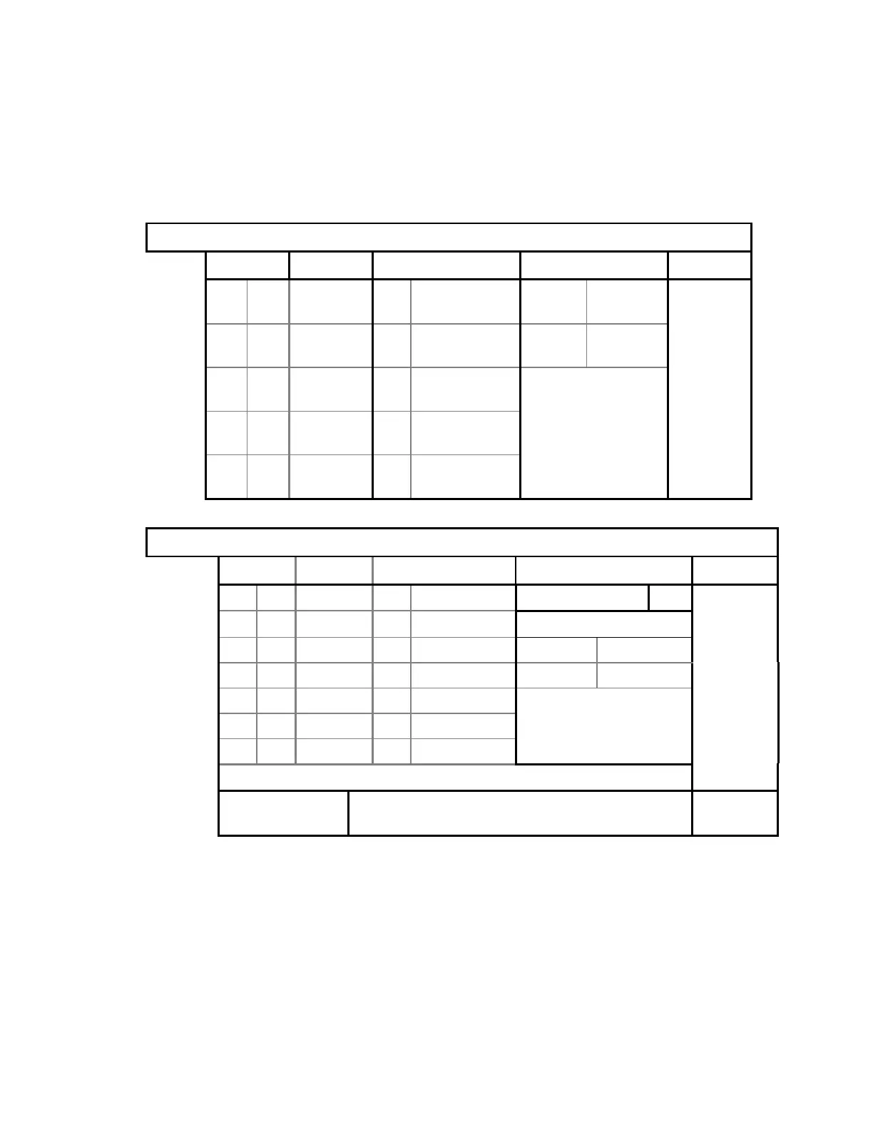
PCB SUMMARY INFORMATION
Power Distribution
LEDs Signal Voltage Source Jacks Refer to...
D1 On +24VDC Ext Power
Console
A/SL All used Figure
D2 On XRAY
ENABLE
- - W/C JP9 not
used
5-14, 5-15
D3 On +15VDC Ext Power
Console
D4 On -15VDC Ext Power
Console
- - +28VDC Ext Power
Console
ADC
LEDs Voltage Voltage Source Jumpers Refer to...
D1 On VCC Int. Voltage Reg. JP3 (GROUND) Out
D2 On +5VDC Int. Voltage Reg. JP5 (HI/LO RES)
D3 On +12VDC Int. Voltage Reg. A/SL In
D4 On -12VDC Int. Voltage Reg. C/W Out Figure
D5 On -5VDC Int. Voltage Reg. 5-13
- - +7VDC Ext C-Arm Int. Bd.
- - +/-15VDC Ext C-Arm Int. Bd.
U14 (LED display) Flickers “1” on bootup, then lock on “2”.
Potentiometer
P3 (A/D GAIN CNTRL) See procedure in
Section 4.
Page 4-24