QDR
4500 Technical Manual
6-8
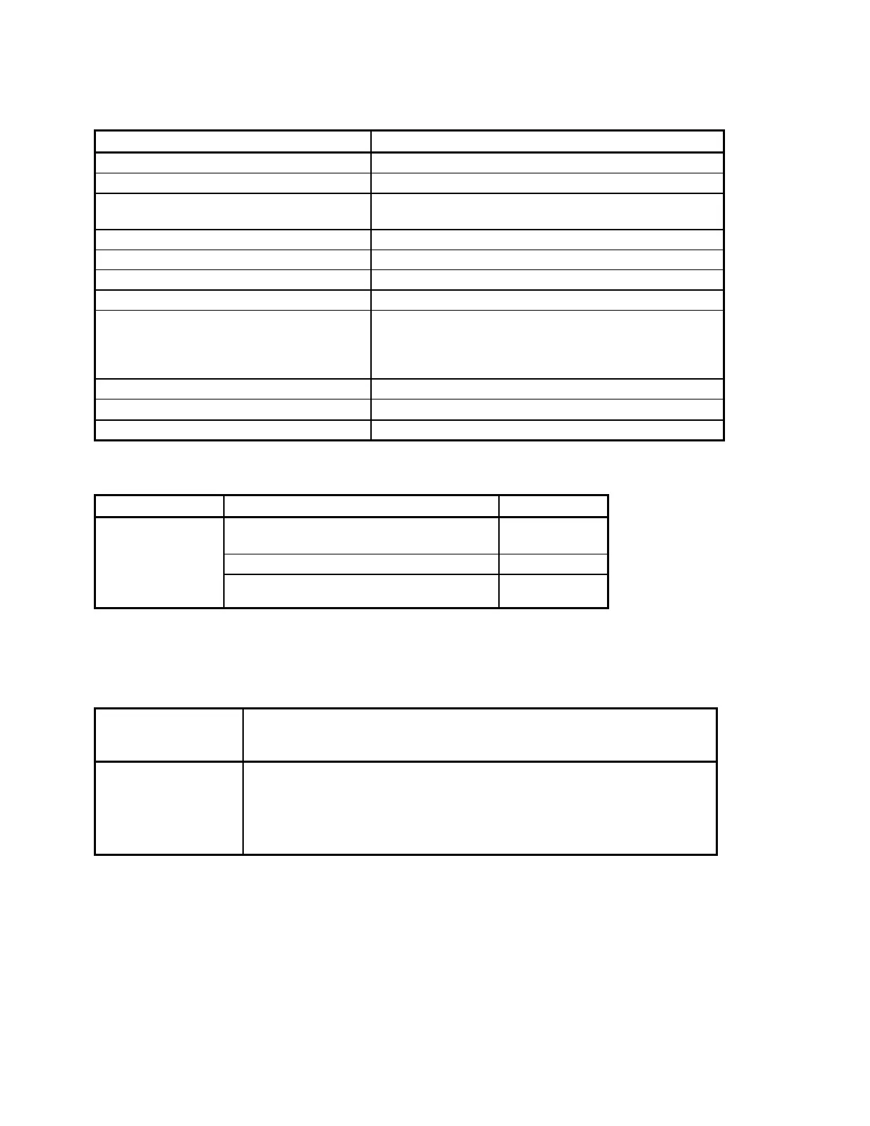
The following suggestions apply to a QDR 4500 system that exhibits no display:
Check... Refer to...
Tube kV peak potential Check Tube kV Peak Potential heading, Section 3
Tube current Check Tube Current heading, Section 3
X-ray production Field Service Preventive Maintenance heading,
Section 7
Signal strength and noise SUSQ in graphic mode,
Filter Drum is turning Figures 5-8, 5-18 through 5-23
Filter Drum belt Figures 5-18, 5-21
Green LEDs on C-Arm Interface board Figure 5-8, Section 8
No display may indicate a bad
Integrator/Multiplexor or Analog to Digital
Converter board
Refer to the Data Acquisition System heading, in
Section 2 of this manual, for block diagrams and
interconnection charts for the Integrator/Multiplexor
and Analog/Digital Converter boards
Check aperture position and aperture belt
Aperture Calibration
heading, Section 4
Also...
Run the hardware checker SQCHECK, 080-0476, F/S Tools disk
TARGETING/LASER PROBLEMS
If... Check... Refer to...
Object being
scanned appears
Detector array. It may be too far forward
or back inside the upper arm assembly.
Figure 5-10
to the left or right
Laser alignment Page 4-22
of the scan
window
Run...
BIGFLAT
DATA COMMUNICATIONS PROBLEMS
Data communications problems occur between the computer and the scanner. Refer to the
following table:
Error messages
usually include the
keywords:
Check the:
Message
Packet
Sent
•
Received
Digital Signal Processor PCB. If IC is not seated properly, replace the
board.
Data, power, and ribbon cables for proper seating.
•
Device states in the SQDRIVER for errors. If a device is stated as
“E_TIMEOUT”, it is suspect.