QDR
®
4500 Technical Manual
1-6
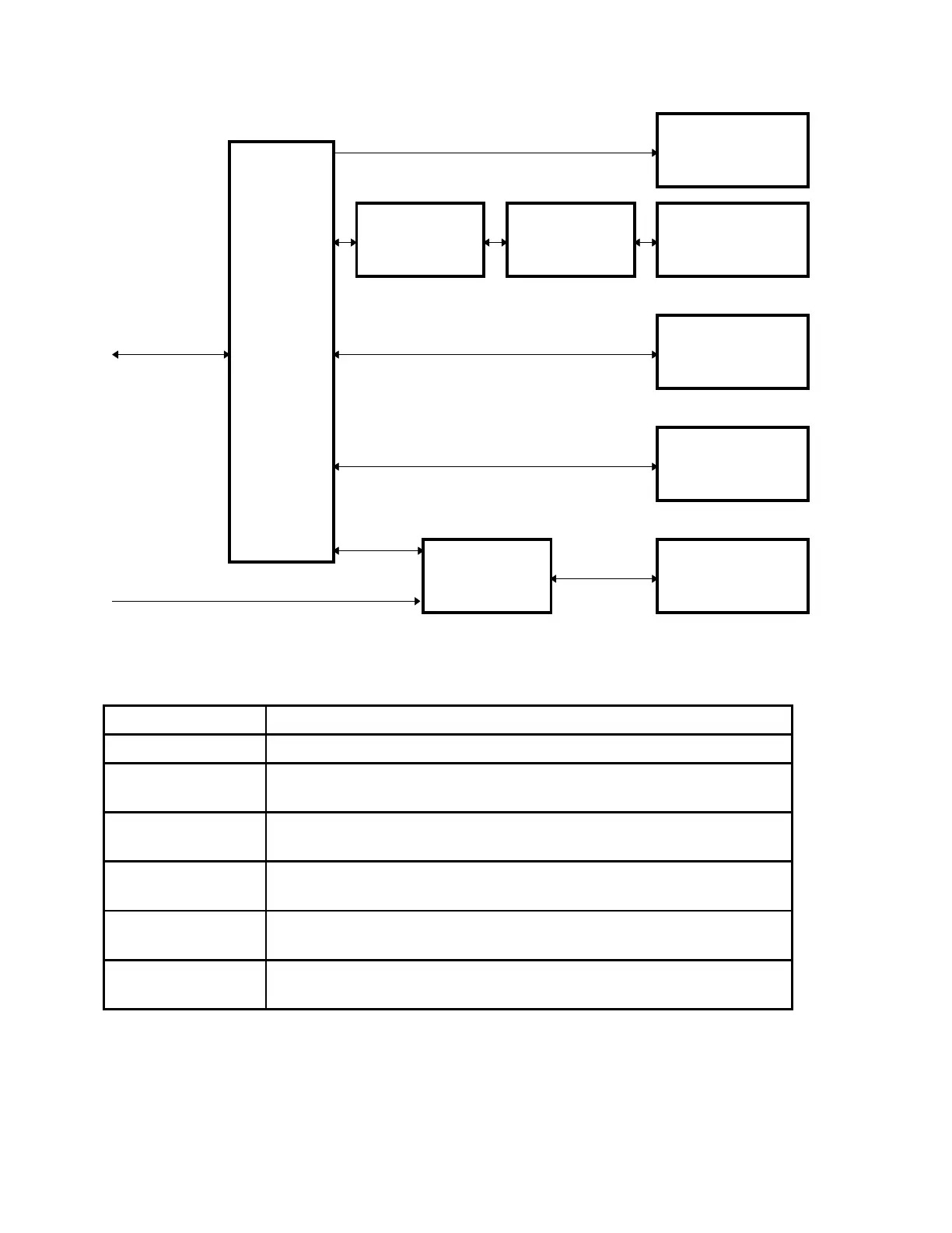
C-ARM
INTERFACE
ANALOG TO
DIGITAL
CONVERTER
INTEGRATOR
MULTIPLEXOR
SILICON
DETECTORS
X_RAY
SOURCE
UNIT
X_RAY
CONTROLLER
APERTURE
MOTOR AND
SENSOR
LASER
ASSEMBLY
DRUM
MOTOR AND
ENCODER PICKUP
TO/FROM
DISTRIBUTION
FROM POWER MODULE
Figure 1-5. QDR 4500 Block Diagram (C-Arm Subsystem)
Block Description
Computer Controls and commands all QDR 4500 hardware modules.
Communications
Controller
Controls the flow of commands to and from the Scanner modules via the
communications bus.
Distribution Board Provides the interconnections between the QDR 4500 Operator's Console
and the Scanner.
Control Panel
Controller
Interfaces the Scanner’s Control Panel to the Operator's Console
computer software.
Control Panel Provides switches (with visual indicators) for moving the Scanner’s C-
Arm and Patient Table. Also provides an Emergency Stop switch.
TZ Drive Motor
Controller
Controls the motion of the Patient’s Table left and right pedestal motors
based on commands from the computer software.