Section 2 - Functional Description
2-13
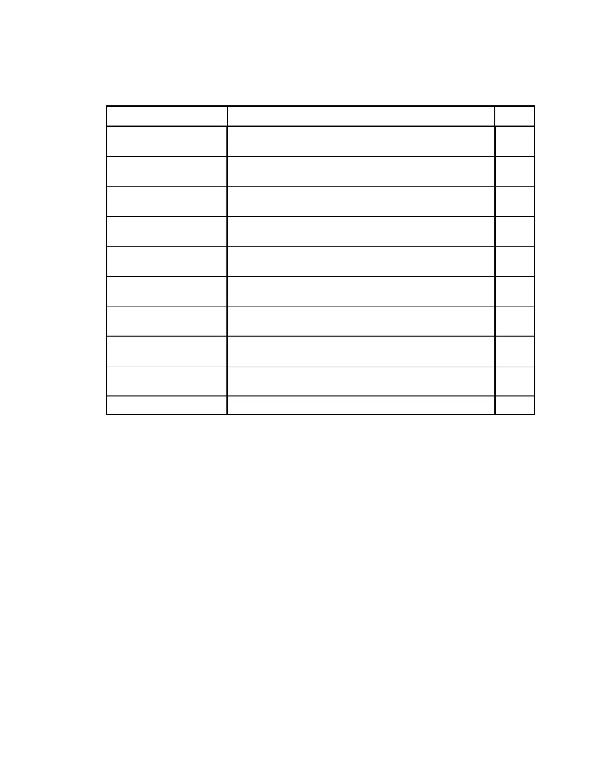
Table 2-8. Distribution Board/Control Panel Controller Interconnection
Descriptions
Signal Description Pin
ARD+
ARD-
Asynchronous Receive Data from the Communications
Controller via the Distribution board.
JP2-4
JP2-5
ATD+
ATD-
Asynchronous Transmit Data to the Communications Controller
via the Distribution board
JP2-7
JP2-8
SYSRESET+
SYSRESET-
System Reset from the Communications Controller via the
Distribution board. Resets the Control Panel Controller.
JP2-10
JP2-11
EMERGENCY+
EMERGENCY-
Emergency TZ drive indicator from the Communications
Controller via the Distribution board.
JP2-13
JP2-14
XRAY_LIGHT+
XRAY_LIGHT-
X-Ray Light from the X-Ray Controller via the C-Arm Interface
and Distribution boards.
JP2-16
JP2-17
EMERGENCY_CPANEL
HW_EMERGENCY_RET
State of the STOP switch and of the collision sensor. (Part of
the safety daisy chain.)
JP2-19
JP2-20
MAN_TZ_UP
MAN_TZ_UP_RET
State of the TABLE switch UP position. JP2-21
JP2-22
MAN_TZ_DOWN
MAN_TZ_DOWN_RET
State of the TABLE switch DOWN position. JP2-23
JP2-24
TILT_A
TILT_B
State of the C-Arm Tilt switch (C-Arm tilted or level) from the
C-Arm Interface via the Distribution board.
JP2-26
JP2-25
+7V DC power for the Control Panel Controller board. JP2-2