Maintenance
8500C/8500C+ System Maintenance Manual A-3
A.4.3 8500C/C+/8520C-36 Balance Test for C-130 Setup
This balance test is similar to the balance test in Section 5.4: therefore, if any failures occur, refer to the
functional test items in the Troubleshooting Guide in Section 5.6.
NOTE: These tests build successively on the first test in this section. Any settings not
mentioned must be left as they were in the previous section.
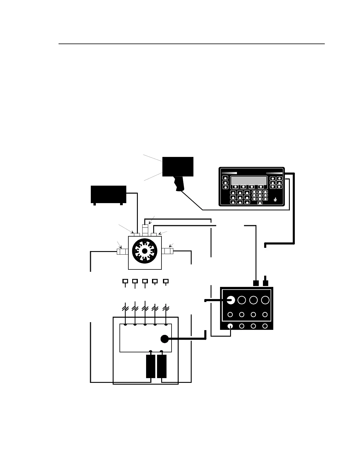
A.4.3.1 Test Setup (with C-130 Nacelle Harness)
a. Connect equipment as shown in Figure A-2.
Figure A-2. Initial 8520C-36 Test Setup (w/C-130 Nacelle Harness)
b. Adjust gap between magnetic pickup and screw to .04 in.
NOTE: Make sure accelerometer cables are free to move so that accelerometer movement is
not inhibited.
ACCELEROMETER
906-7569A
ACCELEROMETER
906-7569A
MAGNETIC PICKUP
3030
CALIBRATOR 11A
POWER
BALANCER
A
B
CD
1234
135M-12 STROBEX
8520C-36
SIGNAL SELECTOR
Y
BALANCER/ANALYZER
CHADWICKHELMUTH
E L M O N T E , C A L I F O R N I
MODEL 8500C
D
J
P
BALANCE
TRACK
#
%
:
SPECTRUM
E
HELP
LOAD
STORE
K
<
Q
>
F
L
R
STATUS
SETUP
-
/
.
PRINT
A
SHOW/HIDE
B
MORE/KEYS
C
STOP
W
Z
X
START
1
4
3
6
G
M
S7
H
2
N
5
8
T
0
V
I
O
9
U
ANNOTATE
8500C BALANCER/ANALYZER
11690 NACELLE HARNESS
5-12 13-20 21-2829-36
10700B HI-TEMP CABLE
10700B HI-TEMP CABLE
CABLE 10811
FILENAME: C-130A.DRW
#6
AFT COMP
#7
TURBINE
#5 COORD
#4 F COMP
#3 ADH
#2 RGB
CABLE 10808
CABLE 10813
CABLE 11517
#1 PROP
POWER SUPPLY 9100A

 Loading...


