4-10 Chadwick-Helmuth A Business Unit of Honeywell International, Inc.
Chapter 4 - System Theory of Operation
4.2.1.2.4 Printer Assembly
The printer assembly is a high resolution thermal graphics printer. The printer prints data onto the 4-3/
8-inch paper roll. The printer is a 320-dot matrix thermal type printer whose print head is controlled by
the printer/disk board. At any time during operation on the aircraft, the user may request a printed
duplicate of the contents of the LCD display by pressing PRINT.
4.2.1.2.5 Disk Drive Assembly
The disk drive assembly is a small, rugged micro-floppy disk drive which provides a mechanism for
archival storage and retrieval of programs and data. The microprocessor in the 8500C allows reading,
writing, and generation of PC/MS-DOS 3.0 (or higher) formatted disks. The capacity of the drive is
720 KB when used with a double sided, double density, micro-floppy disk (8500C/C+) or 1.44 MB
when used with a high-density micro-floppy disk (8500C+ only).
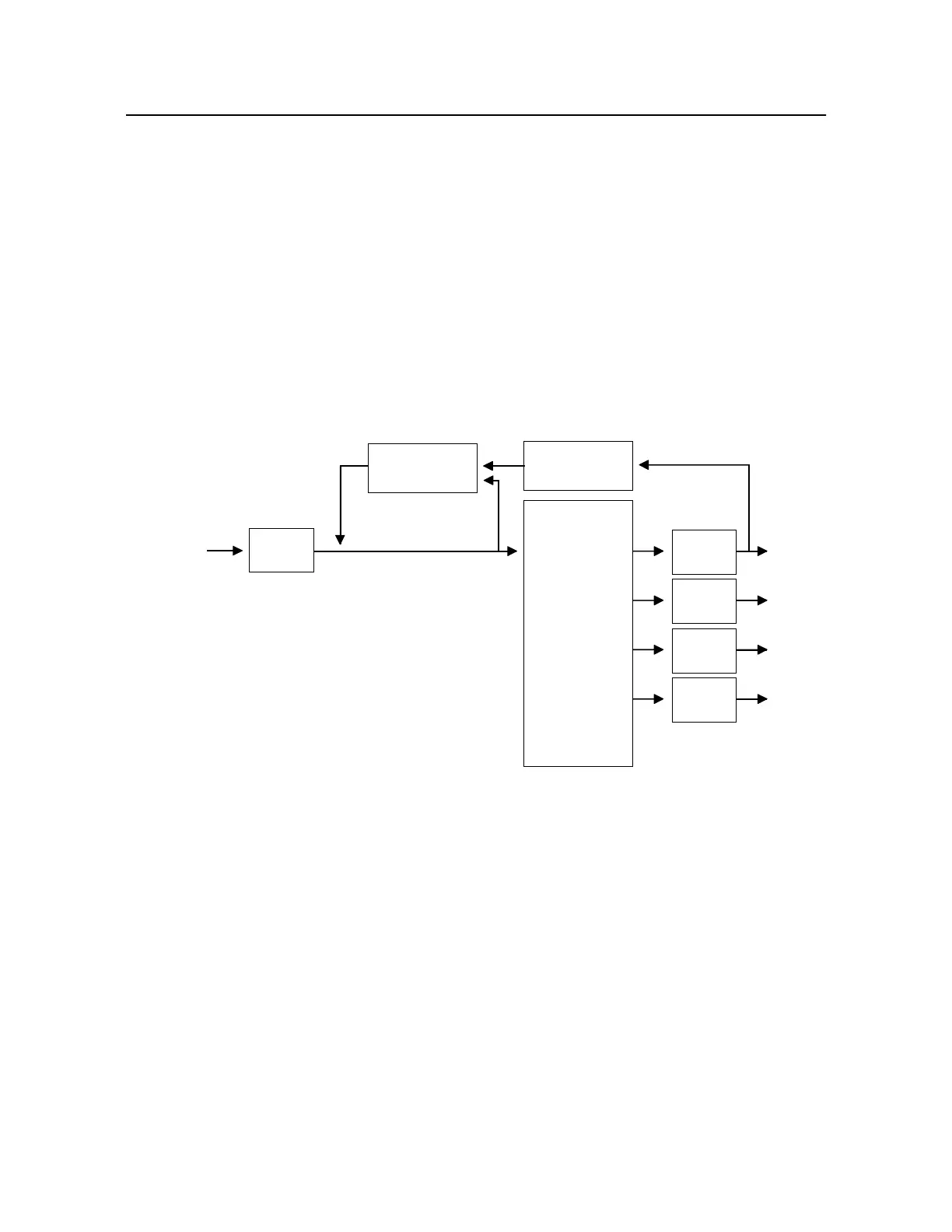
Figure 4-5. Power Supply Board Block Diagram
4.2.2 8520C Signal Selector
The 8520C Signal Selector contains two printed circuit boards: a controller and Velocimeter BIT
(Built-In Test) board, and a power supply board. The controller board selects the appropriate analog
vibration input and/or the appropriate magnetic or photocell pickup input from the aircraft, and
connects it to the 8500C/C+ inputs. The Velocimeter BIT portion of the board determines the presence
of a severe failure (open or short) of a Velocimeter or its cable. The power supply board generates the
DC operating voltages for the other two circuit boards.
4.2.2.1 Controller Board (Figure 4-6)
The controller board routes analog inputs from the Velocimeters and magnetic or photocell pickups for
processing by the 8500C/C+. The inputs are selected by the 8500C/C+.
12 TO 28 VDC
DIODE
BRIDGE
REGULATOR/
PWM
STEP-DOWN
TRANSFORMER
OPTO-ISOLATOR/
LED
RECTIFIER/
FILTER
RECTIFIER/
FILTER
RECTIFIER/
FILTER
RECTIFIER/
FILTER
+5 VDC
+12 VDC
-12 VDC
+5 VDC
FILE: FIG4-5.DRW

 Loading...


