8500C/8500C+ System Maintenance Manual C-1
Appendix C. Chadwick-Helmuth Phase
Measurement Convention
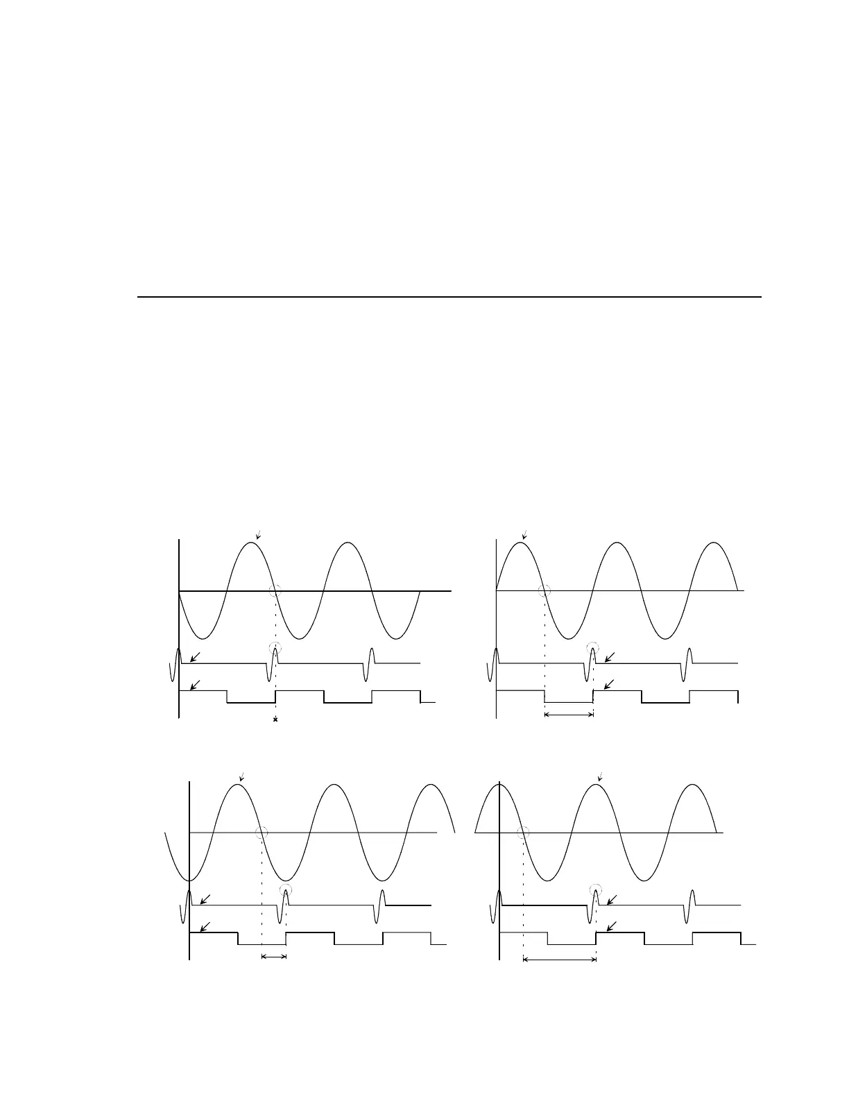
When you use a signal generator to simulate signals to the 8500C/C+, it is important that you
understand how the 8500C/C+ measure phase. As shown in Figure C-1, a zero degree phase interval
measured on the 8500C/C+ occurs when the falling zero crossing of the vibration signal happens at the
same time as the magnetic pickup pulse. Therefore, on an H-P 3561A signal generator, a 180° phase
difference between two output signals would produce a 0° phase measurement on the 8500C/C+. A 0°
phase difference on the H-P would produce a 180° phase difference on the 8500C/C+. If you want to
adjust phase shift when using a signal generator, you must shift the vibration signal and not the
magnetic pickup signal.
Figure C-1. Velocimeter and Magnetic Pickup Signal Phase Relationships
FILE: SINWAVD.DRW
MAG P/U
SQUARE WAVE
SINEWAVE ( VIBRATION INPUT)
PHASE INTERVAL=0
MAG P/U
SQUARE WAVE
PHASE INTERVAL
SINEWAVE ( VIBRATION INPUT)
MAG P/U
SQUARE WAVE
PHASE INTERVAL
SINEWAVE ( VIBRATION INPUT)
MAG P/U
SQUARE WAVE
PHASE INTERVAL
SINEWAVE ( VIBRATION INPUT)
8500C PHASE INDICATION = 0 DEGREE ( 12:00 CLOCK)
(SIGNAL GENERATOR IS SET FOR 180 DEGREE PHASE SHIFT
BETWEEN TWO SIGNALS)
8500C PHASE INDICATION = 90 DEGREES ( 3:00 CLOCK)
8500C PHASE INDICATION = 180 DEGREES ( 6:00 CLOCK)
(SIGNAL GENERATOR IS SET FOR 0 DEGREE PHASE SHIFT
BETWEEN TWO SIGNALS)
8500C PHASE INDICATION = 270 DEGREES ( 9:00 CLOCK)

 Loading...


