Functional Tests
8500C/8500C+ System Maintenance Manual 5-9
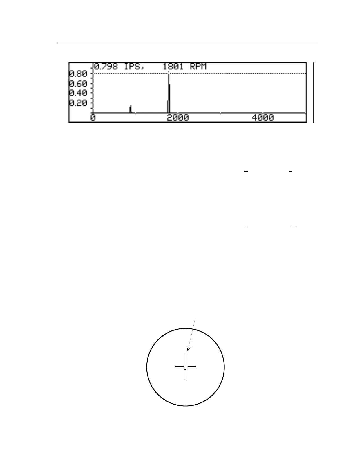
1800 RPM CAM RATE
Figure 5-5. Typical Spectrum Test Displays.
h. Use left or right arrow keys to move cursor (dotted line) to 900 RPM.
i. Verify that readout at top of display shows peak signal is 0.4 +
0.04 IPS at 900 +5 RPM.
J. Switch Calibrator to 1800 RPM CAM RATE.
k. Press START key.
l. Verify that spectrum is displayed (examples in Figure 5-5).
m. Use left or right arrow keys to move cursor (dotted line) to 1800 RPM.
n. Verify that readout at top of display shows peak signal is 0.8 +
0.08 IPS at 1800 +5 RPM.
5.4.1.5 Track Test
a. Press TRACK key on 8500C/C+.
b. Press MORE soft key to select 4 blades.
c. Press START key.
d. Aim Strobex at rotor disk on Calibrator 11A and pull trigger.
e. Verify that stem of “h” at center of rotor disk indicates the following pattern:
f. Release trigger on Strobex.
FILE: CROSS.DRW
DATE: 12/10/90
STEM OF "h"

 Loading...


