• The terminals have cross section area of 0.2 – 1.5 mm
2
and tolerates a maximum cable
length of 3000 ft. It supports solid copper unshielded cable of gauge of 1 mm
2
AWG17.
• The yellow set of buttons that is parallel to terminal bridge is dedicated set of push
buttons for opening-up the respective terminals and making connections using the
communication cables.
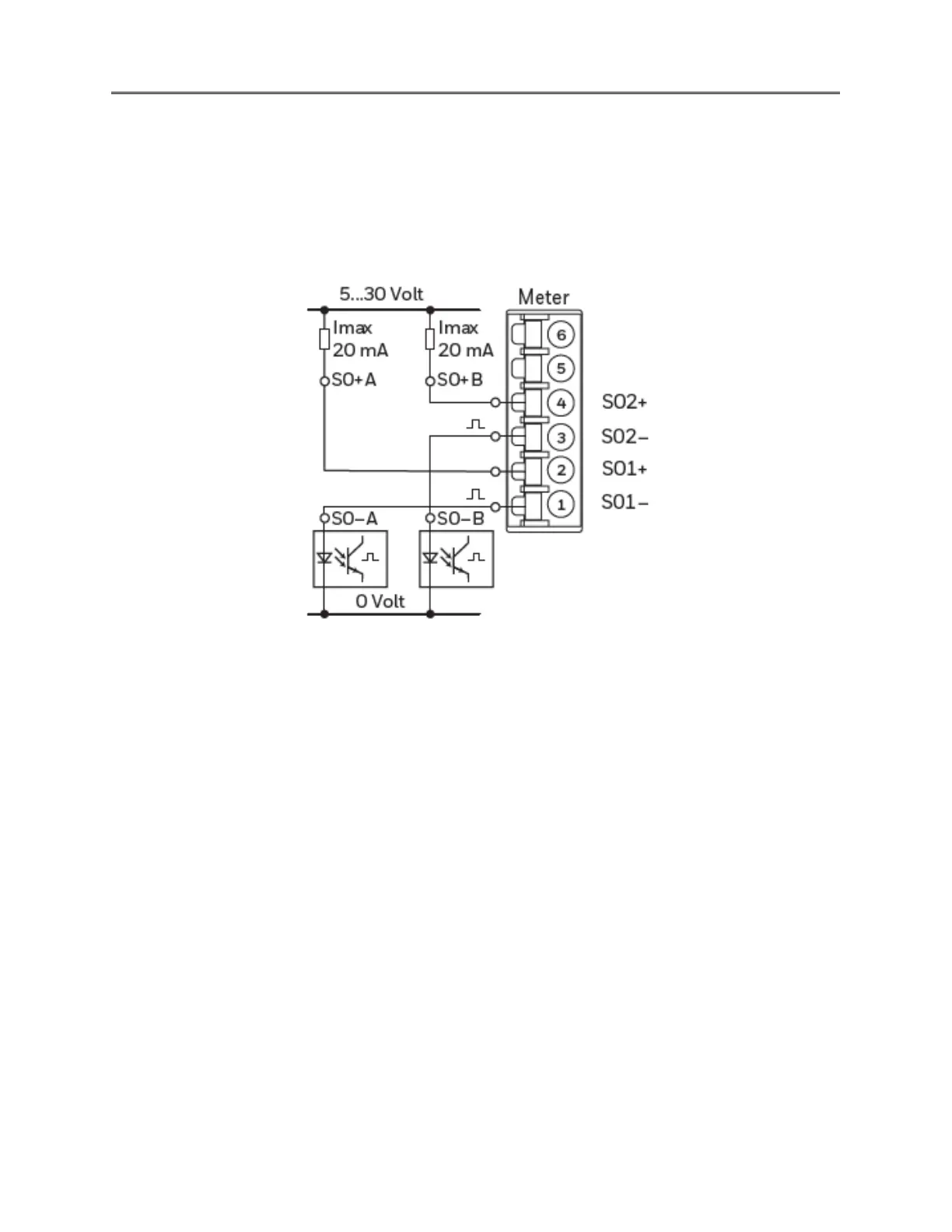
Figure 21. S0 Pulse Output Push-In terminal
The push-in terminal settings shall be done as per the protocol guidelines:
• The S0 output interface requires optocoupler with maximum 30V/20mA and 5V with
impedance of 100 Ω.
• The S0 output settings support maximum of 3280 ft (1000 m) of transmission
distance at 30V/20A with a default pulse width of 30 ms
• Please be careful while using the push buttons as applying excessive pressure may
damage the setup resulting in loose connections and other anomalies.
6.2. Configuration with front panel
The pulse meter connection requires setting up of parameters using the front panel. Setup
the port parameters for communication using the ‘Port 1’ and Port 2’ options and use the
navigation buttons to change the values. Set and save the values of pulse ratio and pulse
duration.
The pulse meter configuration options are available in the ‘Setup’ menu which is accessible
using the front panel navigation. You can change the settings for pulse output using the
‘Setup’ menu. Refer to Section 4.4.3 for more on the ‘Setup’ menu.
 Loading...