GasAlertMaxXT II
User Manual
42
Diagnostics Protection
The detector tests the ambient air (auto-zero) and the test gas that is
applied (auto span) to ensure it meets expected values. Auto-zero sets
the zero-gas level of the sensor. If the target gas is present, the zero
level will be incorrect.
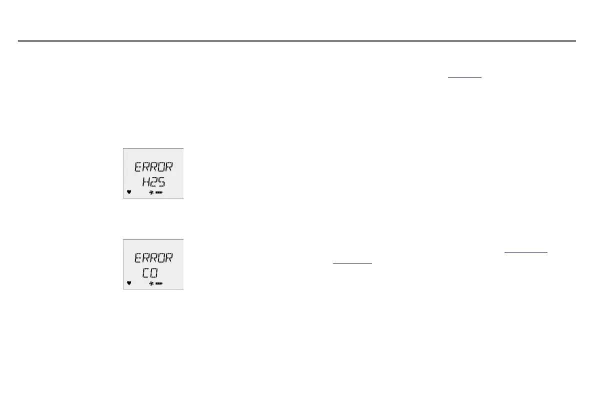
If excessive target gas is present, the sensor(s) will fail and an error
message displays.
In auto span, an error message displays if the target gas does not meet
the expected values.
Sensor(s) that fail to span retain the previous span value and do not
continue the calibration process.
Connecting the Gas Cylinder to the Detector
Refer to the following procedures and Figure 6. to connect the gas
cylinder to the detector for calibration.
Note
Read all of the following procedures before beginning
calibration.
a Caution
The maximum hose length for calibration is 3 ft (0.9 m).
1. Verify the calibration gas being used matches the span
concentration value(s) that are set for the detector.
2. Attach a 0.5 l/min regulator or a demand flow regulator to
the gas cylinder.
3. Connect the calibration hose to the regulator on the gas
cylinder.
4. Begin the calibration procedures. Refer to the Calibration
Procedure section.
 Loading...