MAx panel Fire Detection System
10 M-167.3-Serie-MA-EN / 11.2021
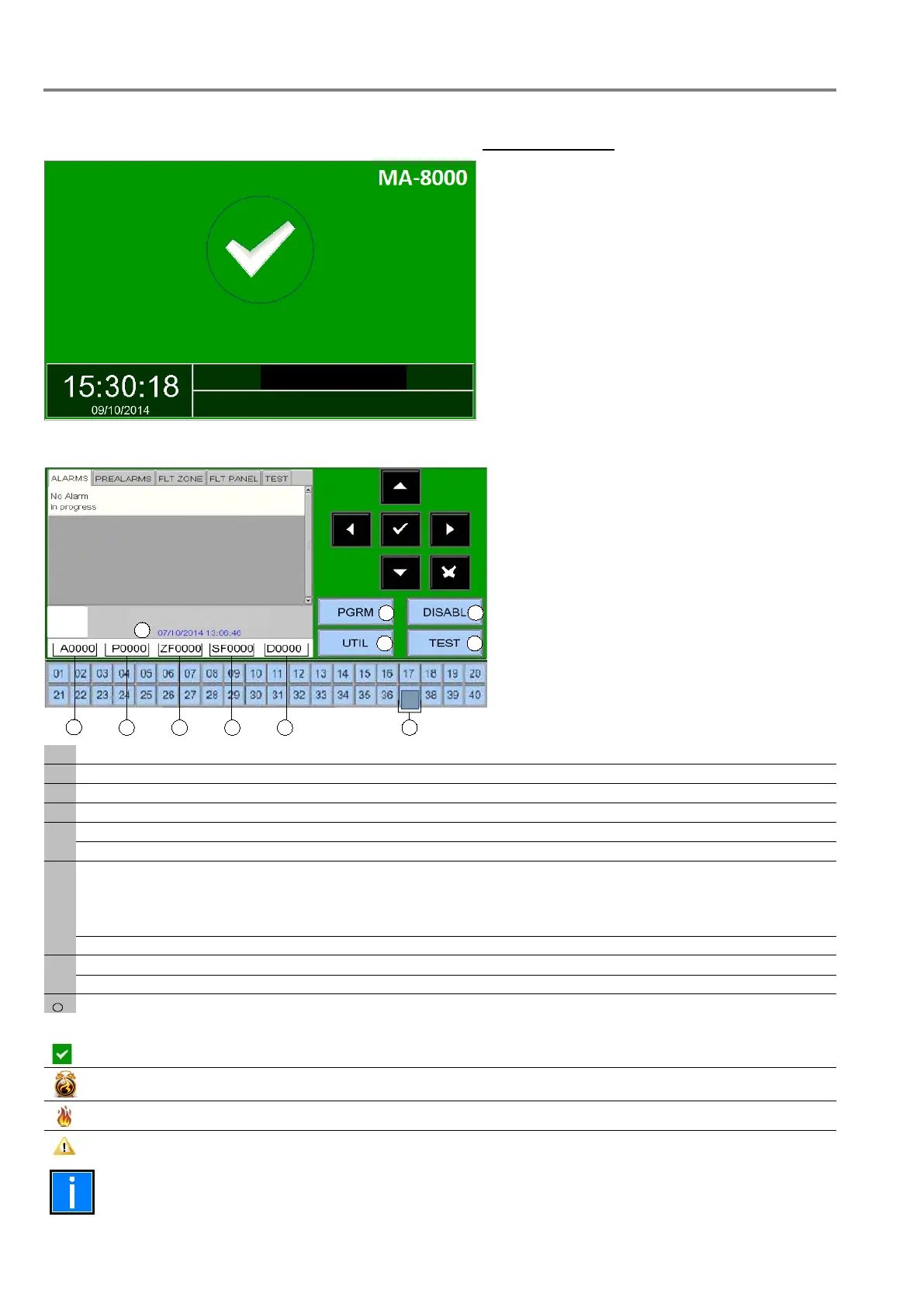
1.5.2 Normal condition
The following screen is displayed when the control panel is in normal condition.
If you tap on the screen, the following screen is displayed.
Virtual zone LED - zonal indication:
Green = OK Dark Blue = TEST
Red = FIRE Light Blue = Disablement
Function associated with PGRM key input of the program menu
refer to Programming menu
Function associated with DISABLE key input of the disable menu
Function associated with TEST key input of the test menu
Function associated with UTIL key input of the utility menu
Icons that indicate the panel conditions
The icon appears if there are no alarms or faults.
If there are pre-alarms the alarm clock icon is displayed.
If there are alarms the fire icon is displayed.
If there are faults this icon is displayed.
The alarm state overrides all other event types if both alarms and faults are present.
 Loading...