36 www.honeywell.com
Installing the MPA2 Panels
Installation
Jumper Settings
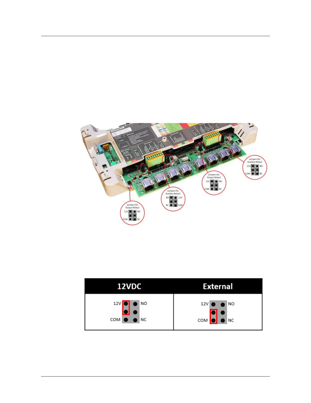
The MPA2 Controller Board provides four jumper sets, one each for output
relay 1, relay AUX 1, output relay 2, relay AUX 2. Each relay has two 3-pin
jumpers associated with it. One jumper selects either external power (EXT)
or self-wetted (on-board, +12V) power to be applied to the relay contact
load. The other jumper is used to select Normally Open (NO) or Normally
Closed (NC) relay contacts. There is a total of eight 3-pin jumpers (two per
relay) on the Controller Board.
Figure 9: MPA2 Controller Board Jumpers
Each relay is associated with two jumpers. As shown below, a relay’s left
jumper configures the relay’s load source (12VDC or External), and the
right relay jumper configures the relay contact type (Normally Closed or
Normally Open).
• Setting the jumpers to configure the power source:
Note: The power source selected by the jumper settings shown above
configure the power source for the relay. It does not configure the power
source for the panel.
• Setting the jumpers to configure the relay contact type: