Notifier SLC Wiring Manual — P/N 51253:U5 12/20/2017 15
SLC Capacity Introduction
1.7 SLC Capacity
The protocol selected for an SLC loop determines the maximum number of devices that can be handled by the loop (see Section 1.5,
“Polling Protocols”, on page 11). Within those limits, the individual control panel may have additional restrictions. See the specific
installation manual for this information.
1.8 SLC Performance
SLC performance (Style 4, Style 6, or Style 7) depends on the configuration of the circuit and the components on the circuit (see
Table 1.2). SLC operation meeting Style 7 requirements isolates each addressable device on the SLC from faults that may occur on the
SLC.
Wiring style requirements are determined by national and local codes. Consult with the Authority Having Jurisdiction before wiring the
SLC. The table below (derived from NFPA 72-2002) lists the trouble conditions that result when a fault exists on an SLC. Additional
information is broken out in Section 2, “Wiring Requirements”, on page 16, and Section 3, “Shielded Wire Termination”, on page 22.
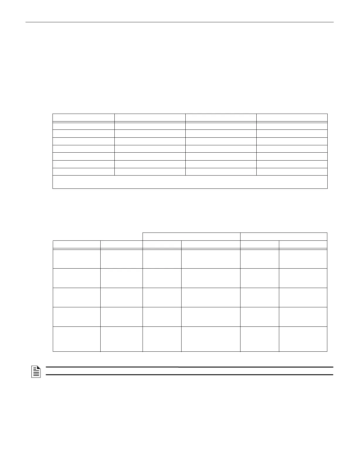
1.9 LED Operation
The table below lists the LED operation on the various devices of an SLC in CLIP (Classic Loop Interface Protocol) Mode and FlashS-
can® Mode. When switching from FlashScan® to CLIP mode, the loop circuit must be powered down for at least 30 seconds to reset
devices to CLIP mode LED operation.
Type of Fault Style 4 Style 6 Style 7
Single Open Trouble Alarm, Trouble Alarm, Trouble
Single Ground Alarm, Trouble (ground) Alarm, Trouble (ground) Alarm, Trouble (ground)
Short Trouble Trouble Alarm, Trouble
Short and open Trouble Trouble Trouble
Short and ground Trouble Trouble Alarm, Trouble
Open and ground Trouble Alarm, Trouble Alarm, Trouble
Communications loss Trouble Trouble Trouble
• Trouble - The control panel will indicate a trouble condition for this type of fault.
• Alarm - The control panel must be able to process an alarm input signal in the presence of this type of fault.
Table 1.2 SLC Circuit Configuration and Performance: Style 4, Style 6, Style 7
CLIP Mode FlashScan® Mode
Control Panel Device Standby Activated Standby Activated
AM2020
AFP1010
Monitor Module
Control Module
Detector
Blinks RED
Blinks GREEN
Blinks RED
RED continuous
2 sec. GREEN, then OFF
RED continuous
N/A
N/A
N/A
N/A
N/A
N/A
AFP-300/AFP-400 Monitor Module
Control Module
Detector
Blinks RED
Blinks GREEN
Blinks RED
RED continuous
GREEN continous
RED continuous
N/A
N/A
N/A
N/A
N/A
N/A
AFP-100
AIM-200
Monitor Module
Control Module
Detector
Blinks RED
Blinks GREEN
Blinks RED
RED continuous
Blinks GREEN
RED continuous
N/A
N/A
N/A
N/A
N/A
N/A
AFP-200 Monitor Module
Control Module
Detector
Blinks RED
Blinks GREEN
Blinks RED
RED continuous
OFF
RED continuous
N/A
N/A
N/A
N/A
N/A
N/A
NFS-320, NFS2-640,
NFS-640
NFS2-3030,
NFS-3030
Monitor Module
Control Module
Detector
Blinks RED
Blinks GREEN
Blinks RED
RED continuous
GREEN continuous
RED continuous
Blinks GREEN
Blinks GREEN
Blinks GREEN
RED continuous
GREEN continuous
RED continuous
Table 1.3 LED Operations
NOTE: In CLIP mode, the LPX-751 and HPX-751 blink GREEN in standby and stay RED when activated.
 Loading...


