58 Notifier SLC Wiring Manual — P/N 51253:U5 12/20/2017
Appendix A: Power Considerations
A.1 Supplying Power to 24 VDC Detectors and NACs
Resistance and Size
To determine the maximum allowable resistance that can be tolerated in supplying power to 24 VDC four-wire devices and NACs, use
the calculations below. These simplified equations assume that the devices are at the end of a long wire run. With the computed resis-
tance and using the manufacturers specifications for the desired wire, select the proper gauge wire for the power run.
For Four-Wire Detectors:
For NACs:
Where:
R
max
= maximum resistance of the 24 VDC wires
V
ms
= minimum supply voltage (see Table A.1 below)
V
om
= minimum operating voltage of the detector or end-of-line relay, whichever is greater, in volts
N = total number of detectors on the 24 VDC supply circuit
I
s
= detector current in standby
N
a
= number of detectors on the 24 VDC power circuit which must function at the same time in alarm
I
a
= detector current in alarm
I
r
= end-of-line relay current
N
b
= number of Notification Appliance Devices
I
b
= Notification Appliance current when activated
The minimum supply voltages produced by Notifier power supplies are listed below:
A.2 Supervising 24 VDC Power
There are options for supervising 24 VDC power, as discussed below.
• Using FlashScan Type Codes with Built-In Power Supervision
• Power Supervision Relay
• Using the FCM-1 module without relay
A.2.1 Using Type Codes with Built-In Power Supervision on the NFS2-3030, NFS-3030, NFS2-
640, NFS-320 and NFS-320SYS
Certain FlashScan type codes have external power supervision built into the software. For details, refer to “Devices Requiring External
Power Supervision” in the appropriate installation manual.
A.2.2 Power Supervision Relay
Power used to supply 24 VDC detectors, notification appliances (using the FCM-1) and two wire detectors (using the FZM-1) can be
supervised with a power supervision relay. This relay, energized by the 24 VDC power itself, is installed at the end of each respective
power run and wired in line with the supervised circuit of any intelligent module.
When power is removed from the relay, the normally closed contacts open the supervised circuit, generating a trouble condition. There-
fore, the relay needs to be installed at the end of the supervised circuit, so it does not disrupt the operating capability of all the devices on
that circuit. The relay can be installed in line with any leg (+ or –) of the supervised NAC or IDC circuit, either a two or a four-wire style.
NOTE: This simplified equation assumes that the devices are at the end of a long wire run.
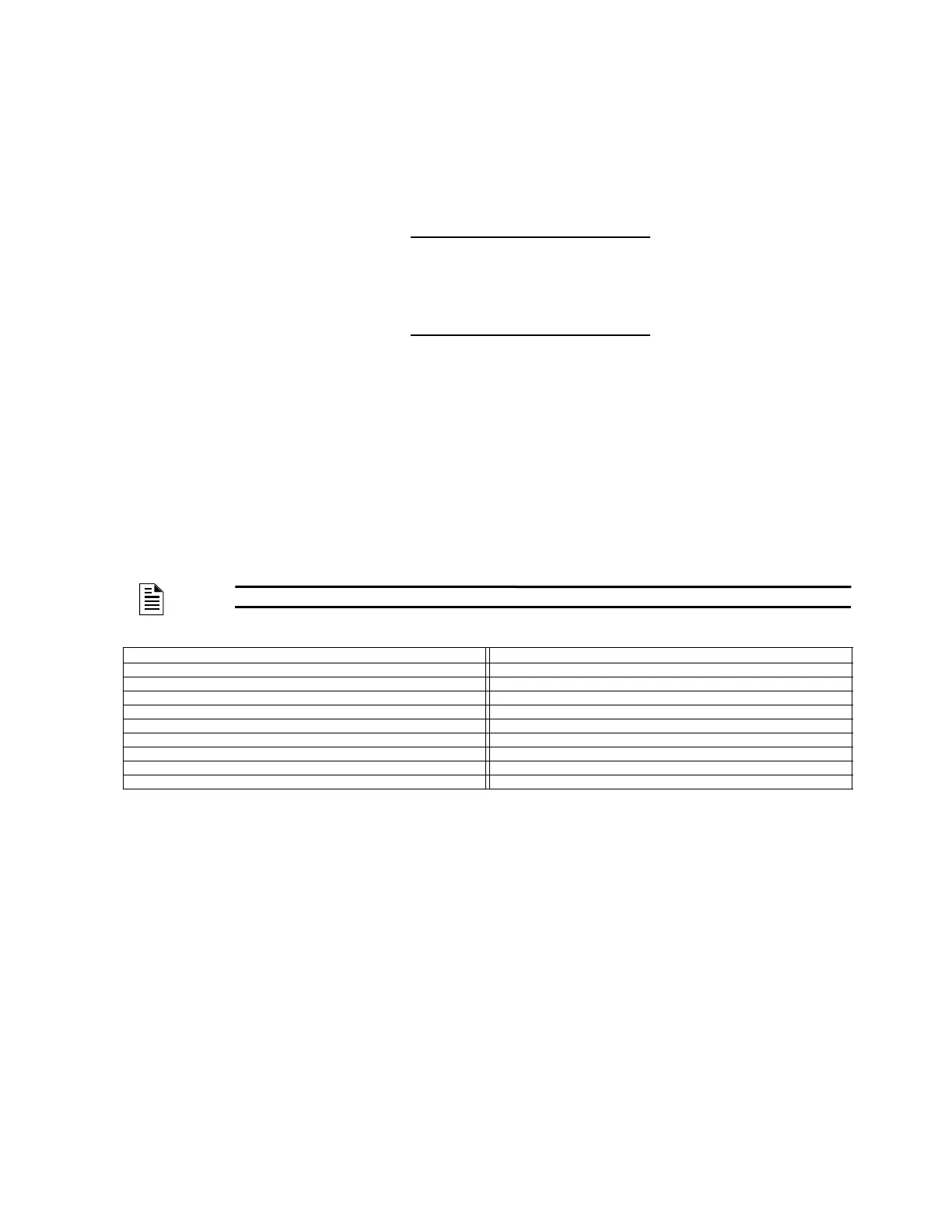
FACP Vms Power Supply Vms
AFP-100 18.1 MPS-24B 20.1
AFP-200 19.4 FCPS-24 19.1
NFS-640 19.15 MPS-24A 19.6
CPS-24 on NFS2-640, NFS-320, or NFS-320SYS 19.48 FCPS-24S6/FCPS-24S8 19.1
MPS-400 19.23
ACPS-2406 19.8
AMPS-24 20.14
ACPS-610 19.57
APS2-6R 20.0
Table A.1 Minimum Supply Voltage
R
max
=
(V
ms
- V
om
)
(N)(I
s
) + (N
a
)(I
a
) + (I
r
)
R
max
=
(V
ms
- V
om
)
(N
b
)(I
b
)
 Loading...


