Notifier SLC Wiring Manual — P/N 51253:U5 12/20/2017 19
Control Panel Terminal Blocks Wiring Requirements
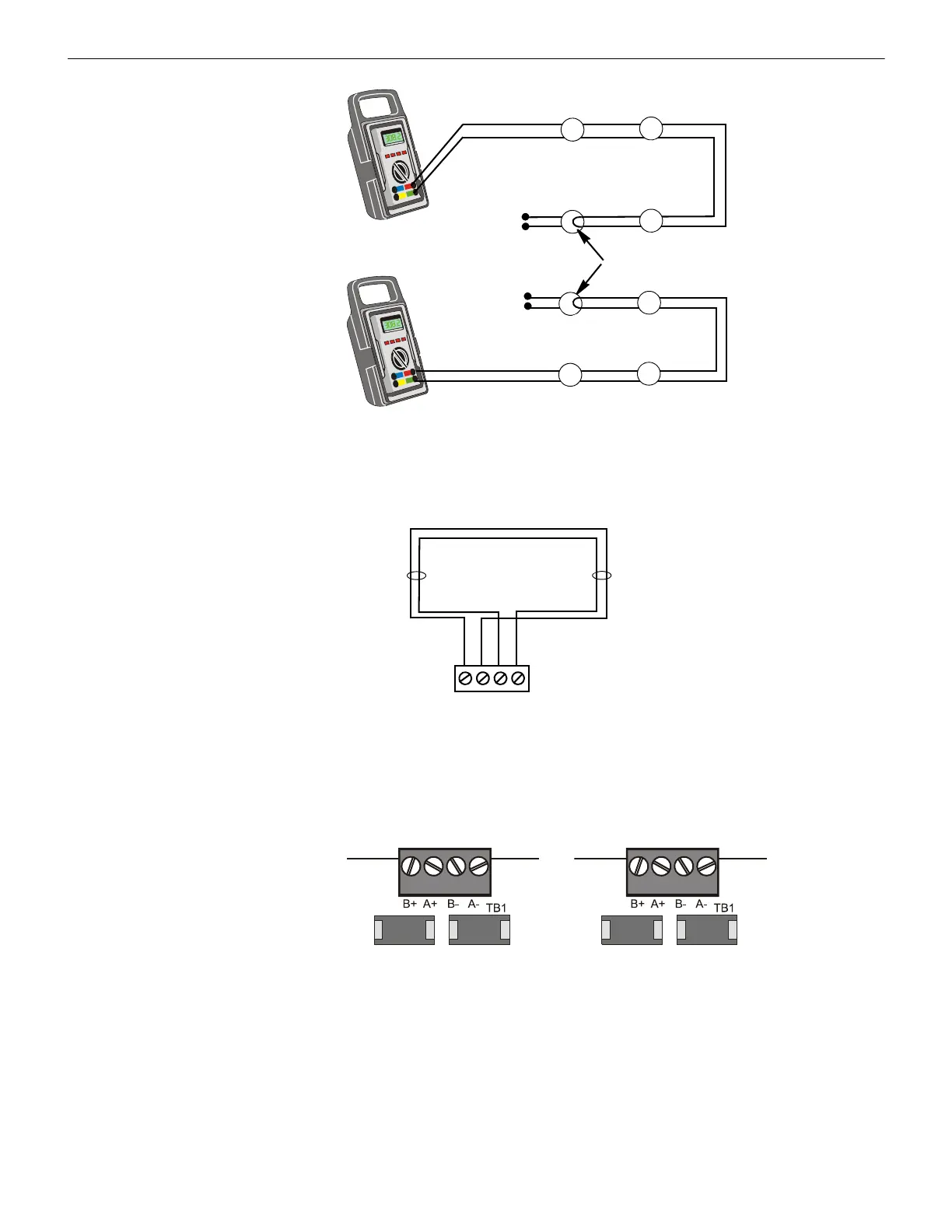
2.3.2 Measuring Total Wire Length
The total wire length in a four-wire SLC cannot exceed the limits set forth in each system’s instruction manual. The figure below identi-
fies the output and return loops from SLC terminal on the control panel:
2.4 Control Panel Terminal Blocks
2.4.1 NFS2-3030 and NFS-3030 with LCM-320, LEM-320
The NFS-3030/NFS2-3030 supports up to five pairs of loop control and expander modules, providing from one to ten SLC loops. Loops
can be either CLIP mode or FlashScan mode. SLC loops connect to TB1 on the LCM-320 or LEM-320.
SLC-meas5.wmf
SLC Out
SLC Return
Short Point
SLC Return
SLC Out
STEP 2
STEP 3
First Device
Last Device
Last Device
First Device
Figure 2.3 Measuring DC Resistance of a Four-Wire SLC
B–A+B+ A–
SLC channel B
(output loop)
SLC channel A
(return loop)
SLC Terminal Block
Figure 2.4 Measuring the Wire Length of a Four-Wire SLC
SLC Loop Connections
on Loop Expander Module
SLC Loop Connections
on Loop Control Modules
LEM320-SLC-TB.wmf
Figure 2.5 NFS2-3030, NFS-3030 SLC Loop Connections and Wiring
 Loading...


