SPYDER MODEL 5 ENGINEERING TOOL – USER GUIDE
31-00282ES-01 56
Procedure
1. Double-click On Board I/O in the tree, and then select the Wire Sheet view.
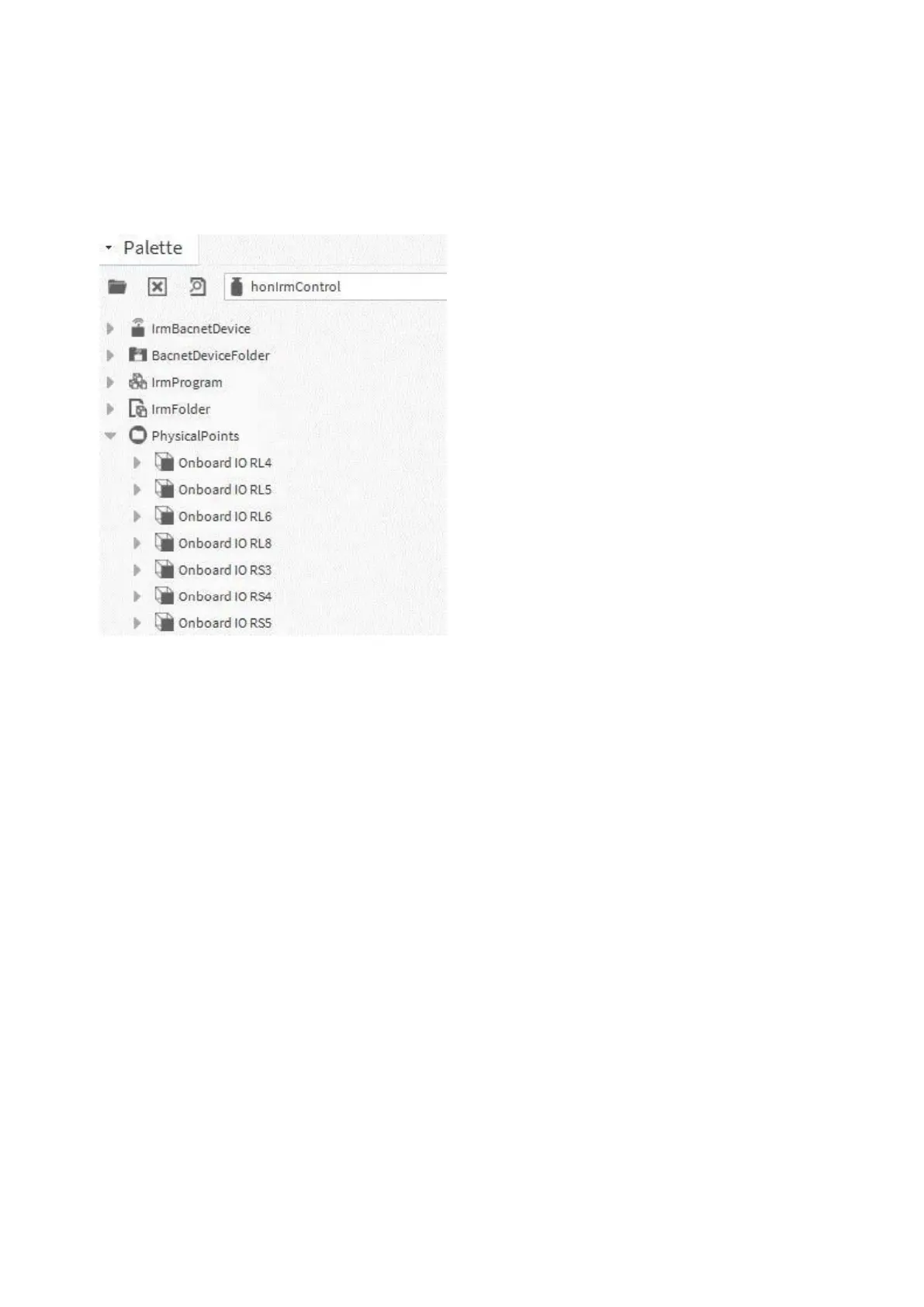
2. Open the “honIrmControl” palette.
3. From the palette, add single physical terminals manually or a pre-defined template to the wire sheet via drag & drop.
Pre-defined templates are matched to particular controller models. The following physical terminals and templates
are available:
4. Create/change the layout by applying desired steps such as connecting, adding, deleting, and moving terminals,
and/or adding and deleting connections.
Synchronization Check
Any modifications on the On Board I/O wire sheet are detected by the control manager. Modifications can be any of the
following:
• Added item
• Deleted item
• Moved item
• Added connection
• Deleted connection
• etc.
As result, all modified items will be not in sync with the application in the controller and hence indicated by a yellow
“warning” symbol on the item.

 Loading...