27
Connecting & Powering Electric Lock
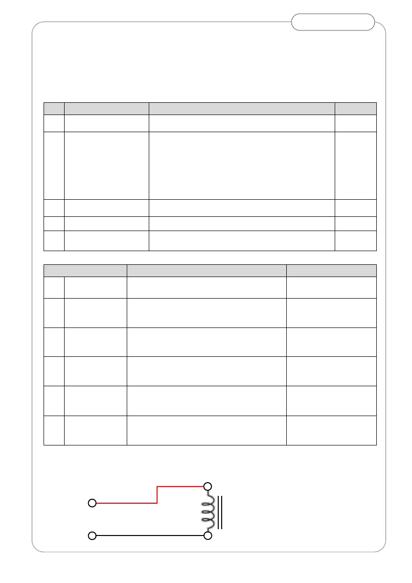
Powered electric locks connect to terminal M (Fig19).
Check lock power is within output limits (12/24Vdc, 15W)
Set parameters 9/10/11/12/14 according to lock type
0 = No Lock
1 = Strike fail secure without power
2 = Maglock (24VDC type only)
3 = Solenoid
4 = Motorised
5 = strike with relock at power off
6 = Maglock with delayed re-energise (24VDC only)
0 to 9 dependent on the type of electric lock
0 = Disabled 1 = One Radar
2 = Two Radars 3 = One Radar and two Radars
De-energised after delay (Id11)
Relocks mechanically in closed position.
Door opens after delay (Id11)
Re-energised when door near to closed
Only use 24Vdc rated Mag-locks up to 625mA
Door opens after delay (Id11)
Re-energised when door fully closed
Door opens after delay (Id11)
Re-energised to lock when door is fully closed
Unlocks on power (impulse)
Door opens after delay (Id11)
De-energised beyond 10° of opening
Door opens after set delay (Id11)
Re-energised after door reaches closed
Only use 24Vdc rated Mag-locks up to 625mA
Wire lock to terminal M observing polarity.