Figures
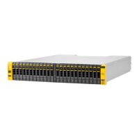
1 HP M6710 Drive Enclosure (2U24).....................................................................................10
2 HP M6720 Drive Enclosure (4U24).....................................................................................10
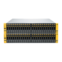
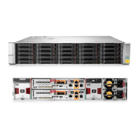
3 HP 3PAR StoreServ 7400 Controller Nodes.........................................................................11
4 HP 3PAR StoreServ 7400 Node:Slot:Port Legend..................................................................12
5 Location of Controller Node Ports.......................................................................................13
6 I/O Module Numbering for HP M6710 (2U) and HP M6720 (4U) Drive Enclosures..................14
7 PCM Numbering.............................................................................................................14
8 PCMs in a HP M6710 (2U) and HP M6720 (4U) Drive Enclosures...........................................15
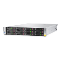
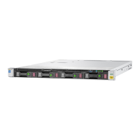
9 HP 3PAR Service Processor DL 320e...................................................................................15
10 Location of Bezel LEDs......................................................................................................16
11 Location of Disk Drive LEDs................................................................................................17
12 Location of Controller Node PCM LEDs...............................................................................18
13 Location of Drive PCM LEDs...............................................................................................19
14 Location of HP M6710/M6720 I/O Module LEDs................................................................20
15 I/O Module Power and Fault LEDs.....................................................................................20
16 Location of External Port Activity LEDs.................................................................................21
17 Location of Controller Node LEDs.......................................................................................22
18 Location of Ethernet LEDs .................................................................................................22
19 Location of FC Port LEDs....................................................................................................23
20 Location of SAS Port LEDs..................................................................................................23
21 Location Interconnect Port LEDs..........................................................................................24
22 Location of Fibre Channel Adapter Port LEDs........................................................................25
23 Location of CNA Port LEDs................................................................................................25
24 16 G FC Adapter LEDs.....................................................................................................26
25 10 G Ethernet Adapter LEDs..............................................................................................27
26 1 G Ethernet Adapter LEDs ...............................................................................................27
27 Front Panel LEDs...............................................................................................................28
28 Rear Panel LEDs...............................................................................................................29
Tables
1 Storage System Expansion Cards.......................................................................................12
2 Description of Controller Node Ports...................................................................................13
3 Description of Bezel LEDs..................................................................................................16
4 Description of Disk Drive LEDs............................................................................................17
5 Description of Controller Node PCM LEDs...........................................................................18
6 Description of Drive PCM LEDs...........................................................................................19
7 Description of I/O module Power and Fault LEDs..................................................................20
8 Description of Controller Node LEDs...................................................................................22
9 Description of Ethernet LEDs..............................................................................................22
10 Description of FC Port LEDs................................................................................................23
11 Description of SAS port LEDs.............................................................................................24
12 Description of Interconnect Port LEDs...................................................................................24
13 Description of Fibre Channel Adapter Port LEDs....................................................................25
14 Description of CNA Port LEDs............................................................................................25
15 16 G FC Adapter LEDs.....................................................................................................26
16 10 G Ethernet Adapter LEDs..............................................................................................27
17 1 G Ethernet Adapter LEDs................................................................................................27
18 Front panel LEDs..............................................................................................................28
19 Rear panel LEDs..............................................................................................................29
 Loading...