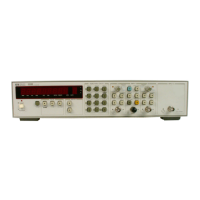
CHANGE (4) SERIES 2826A
Table 6-2. A2 Front Panel Board Assembly Replaceable Parts:
Change
A2MP44/MP45 from 5041-0285 to 5041-0318 (Color change from light to medium gray.)
Table 6-2. Chassis Parts:
Change 2360-0209 to 2360-0129 SCREW-MACHINE 6-32 1-IN-LG PAN-HD POZI.
Delete 2190-0006, WASHER-LOCK.
CHANGE (5) (2704A00147
thru
2804A00838)
Make this change for instruments that contain the Revision B and C, A1 Main Board Assembly.
Table 6-2, Replaceable Parts:
Delete
AlC103,0180-3775, CAPACITOR-FXD 3300UF +30 -10% 16VDC
AL.
Delete AlC104,0160-0576, CAPACITOR-FXD .1UF +20% SOVDC CER.
Delete
AlCR40,1902-0951, DIODE-ZNR 5.1V 5% DO-35 PD
=
.4W TC
=
+
.065%
Delete AlR142,0698-0082, RESISTOR 464 1% .125W F TC
=
Ot100.
Delete AlR143,2100-4158, RESISTOR-TRIM 10K 10% TKF
T%P
ADJ-2STRN
Delete AlR144,0757-0290, RESISTOR 6.19K 1% .125W F TC
=
0+100.
Delete AlR331,0757-0280, RESISTOR 1K 1% .125W F
TC=W~&.
Change AIR291 and R295 from 0757-0465 (100K) to 0757-0465T~E~1~~0~ 100K 1% .125W
F
TC= Ot100.
-
Change AIR293 from 0757-0433 (11K) to 0757-0443, RESISTOR 11K 1% .125W F TC=Ot100.
-
Delete AlR294,0757-0199, RESISTOR 21.5K 1% .125W F TC
=
Ot100.
-
Delete AlU292,1826-1338, IC MISC 8-DIP-P PKG.
Add
AlU291,18%-0412, IC COMPARATOR PRCN DUAL 8-DIP-PKG.
Paragraph 8-218. Power-up RESET Circuit Description:
Change paragraph 8-219 to read as follows:
8-219. The RESET circuit
U291, is a comparator with an open collector output that synchronizes the
HP-IB MCU
(U17), Measurement MCU (U19), and MATE Microprocessor (U702). U291 also keeps
the reset
limes low for a minimum of 100 ms. The 100 ms delay allows the clock
in
the HP-IB MCU time
to stabilize. Resistors R293 and R294 form a voltage-divider that applies approximately 3 volts to the
plus side of
U29lA (pin 3). Resistor R291 and capacitor C709 provide an RC time constant that applies
a rising voltage to the negative side of
U291A (pin 2). The rising voltage on pin 2 equals the voltage on
pin 3 in approximately 100 ms When the voltage on the negative input goes above the voltage on the
positive input, the output (pin 1) goes LOW. When pin
1
goes LOW, pin 7 of U291B goes HIGH and
resets the HP-IB MCU, Measurement MCU, and MATE Microprocessor.
Figure 8-19. HP
5334B Component Locator:
Delete
C103, C104, CR40, R142, R144, and R143, which are the components of the Oven Oscillator
Fine Adjust circuit located near the Option 010 Oven Oscillator.
HP
5334B
-
Service
Manual
7-4

 Loading...