Model 7475A
1-A-2-IA
D
--7
>-
4
•
49
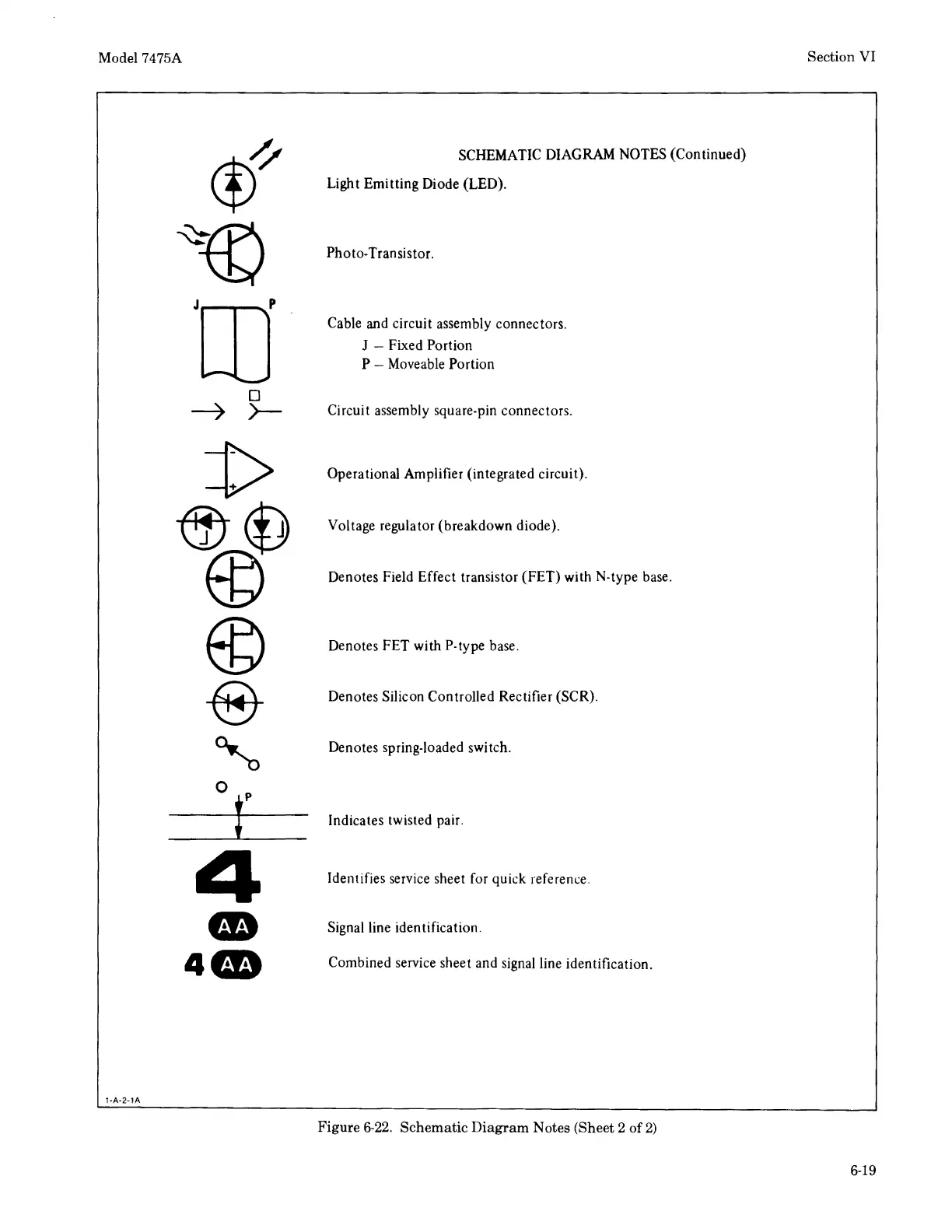
SCHEMATIC DIAGRAM NOTES (Continued)
Light Emitting Diode (LED).
Photo-Transistor.
Cable and circuit assembly connectors.
J - Fixed Portion
P - Moveable Portion
Circuit assembly square-pin connectors.
Operational Amplifier (integrated circuit).
Voltage regulator (breakdown diode).
Denotes Field Effect transistor
(FET)
with N-type base.
Denotes
FET
with P-type base.
Denotes Silicon Controlled Rectifier (SCR).
Denotes spring-loaded switch.
Indicates twisted pair.
Identifies service sheet for quick reference .
Signal line identification.
Combined service sheet and signal line identification.
Figure
6-22.
Schematic
Diagram
Notes (Sheet 2 of
2)
Section
VI
6-19