Table 5 Optional Network Connectivity, Speeds and Technologies (continued)
Fiber (single
mode)
10-Gig ER
Not Applicable
Copper
(twinaxial)
40-Gig Direct
Attach 1/3/5 m
40 Gbps
MPO
Fiber
(multimode)
40-Gig SR4
MPO
Fiber
(multimode)
40-Gig ESR4
LC
Fiber (single
mode)
40-Gig LR4
RJ-45
Copper
(twisted pair)
Smart Rate
Smart Rate
1/2.5/5/10
Gbps
1
For supported transceivers, visit http://www.hpe.com/networking/support .
• In the first textbox, type J4858 (for 100-Mb and Gigabit information), J8436 (for 10-Gigabit information), or JH231
(for 40–Gigabit information).
• Select any of the products that display in the dropdown list.
• Select Support Center. Then click on Manuals, followed by View All to and find the Transceiver Support
Matrix.
For technical details of cabling and technologies, see Cabling and Technology Information.
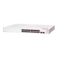
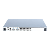
Management Ports
Console Ports
There are two serial console port options on the switch, an RJ-45 or Micro USB. These ports are
used to connect a console to the switch either by using the RJ-45 serial cable supplied with the
switch, or a standard Micro USB cable (not supplied). The Micro USB connector has precedence
for input, so if both cables are plugged in, the console output is echoed to both the RJ and
Micro-USB ports. But, the input is only accepted from the Micro-USB.
For more information on the console connection, see “10. (Optional) Connect a Management
console” (page 44). The console can be a PC or workstation running a VT-100 terminal emulator,
or a VT-100 terminal.
Auxiliary (Aux) Port
An auxiliary port for processing a USB command file or downloading switch software code. This
port uses a USB Type A connector, but does not comply with all USB protocols and standards.
Switch and Port LEDs on Front of the switches
• Front of Switch Status and Mode LED Behavior describes the switch chassis and Flex Port
status LEDs and also the Switch Mode LEDs.
• Table 9 (page 15) describes the switch Port LEDs and their different mode behaviors.
Front of the Switches 11

 Loading...