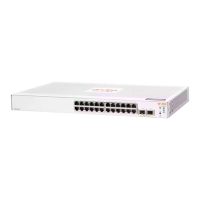
4. Tighten the captive screws until they are snug – do not overtighten them.
Figure 12 Installing the Module
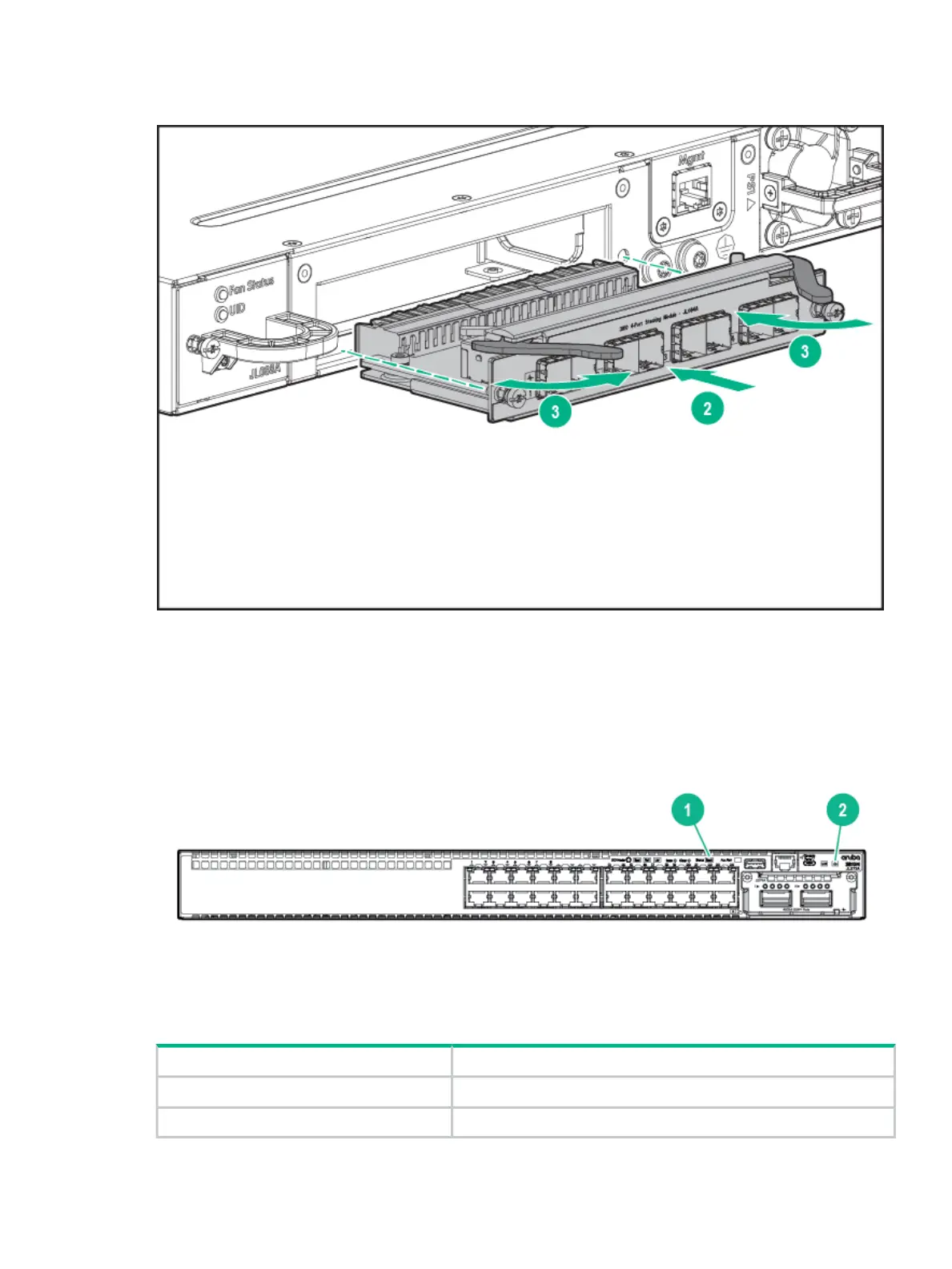
Verifying the Module is Installed Correctly
Observe the Back and Global Status LEDs on front of the switch, and the Module Status LED
on the module to verify module is installed properly.
Figure 13 Location of Module Status LEDs
Table 17 Location of Module Status LEDs Label and Description
DescriptionLabel
Back LED1
Global Status LED2
If the module is installed properly and the switch is powered on, the module undergoes a self
test during the normal switch boot up process. You can use the LEDs to determine that the
Installation Procedures 35

 Loading...